Facebook
 Google
 GitHub
 Linkedin
The Voice Echo: An Arduino Audio Project
This project brief explains how to construct a PCB-based audio-processing platform with an ATmega328 microcontroller. A link to Arduino code for creating an audio echo is also provided.
The Voice Echo Project consists of an Arduino-compatible microcontroller, audio input/output circuitry, and an optional microphone pre-amplifier. 3.5 mm stereo EP sockets are provided for the audio input and output signals. It is based on the excellent echoTrek Digital Delay/Echo project, which can be found on the Arduino project hub. A special thanks to Julio Cesar, a.k.a. CesarSound, for creating it!
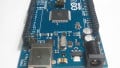
While the original echoTrek was built on a breadboard, my version (Figure 1) uses a PCB.
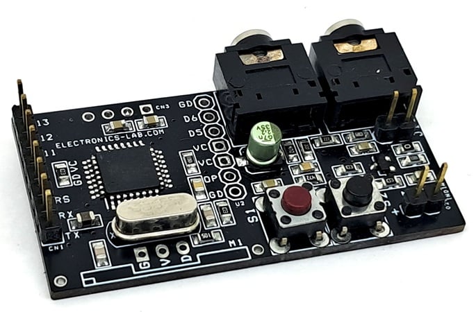
Figure 1. The fully assembled Voice Echo board.
The idea is to simplify the hardware and make audio connections easier. Just upload the Arduino code to the microcontroller, connect the audio source, and you'll experience the echo effect immediately. The project is designed to be simple and user-friendly, allowing anyone to enjoy it.
Project specifications are as follows:
- Power input: 5 V DC.
- 3.5 mm stereo EP socket for audio input and output.
- Onboard tactile switch for echo effects.
- Onboard connector for bootloader and Arduino programming.
- PCB dimensions: 52.55 x 27.78 mm.
Schematic and Bill of Materials
Figure 2 shows the schematic for the Voice Echo project. Clicking on the image will open a larger, higher-resolution version in a new tab.
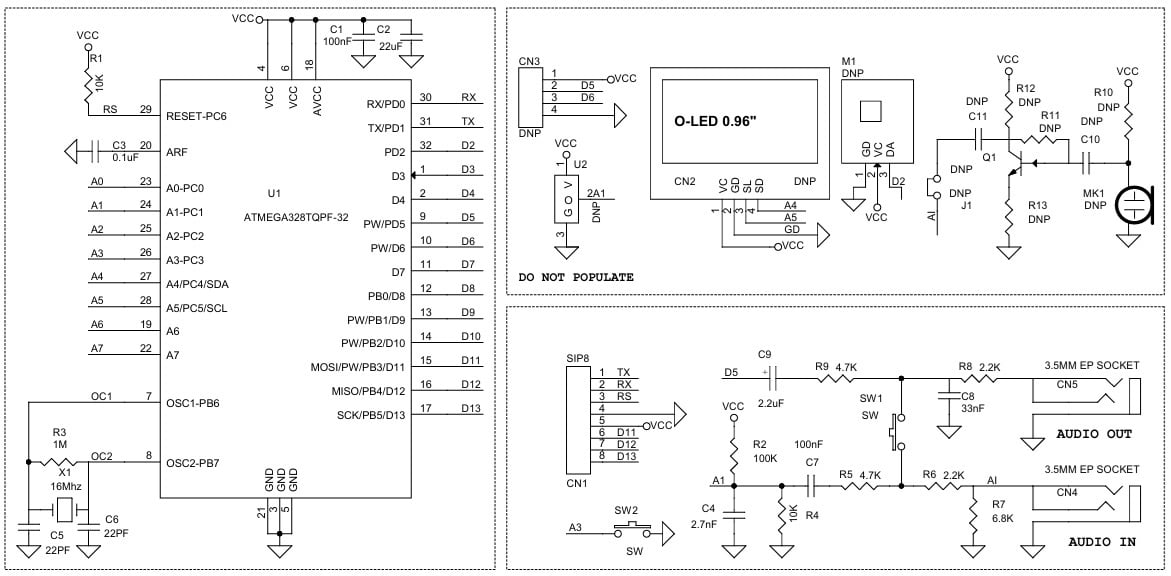
Figure 2. [click to enlarge] Schematic for the Voice Echo project.
The 'Do Not Populate' section of the schematic includes the following optional features:
- microphone preamplifier.
- 0.96 inch OLED display.
- U2 analog sensor connections.
- 433 MHz RF transmitter module.
- D5/D6 PWM output lines.
The optional features allow the Voice Echo hardware platform to be repurposed for other audio-related projects, such as a sound-activated switch or sound-level meter. Because the components are optional, they are not included in the project BOM (Table 1).
Table 1. BOM for the Voice Echo.
| REF. | DESC. | QNTY. | MANUFACTURER | SUPPLIER | SUPPLIER PART NO. |
| CN1 | 8 PIN MALE HEADER PITCH 2.54mm | 1 | WURTH | DIGIKEY | 732-5321-ND |
| Q1, MK1, M1, J1, U2, CN2, CN3, R10, C10, R11, C11, R12, R13 | DNP | 13 |
|
|
|
| CN4,CN5 | 3.5mm EP STEREO SOCKET | 2 | CUI | DIGIKEY | CP1-3525N-ND |
| C1,C7,C3 | 100nF/50V CERAMIC SMD SIZE 0805 | 3 | YAGEO/MURATA | DIGIKEY |
|
| C2 | 22uF/10V CERAMIC SMD SIZE 0805 | 1 | YAGEO/MURATA | DIGIKEY |
|
| C4 | 2.7nF/50V CERAMIC SMD SIZE 0805 | 1 | YAGEO/MURATA | DIGIKEY |
|
| C5,C6 | 22pF/50V CERAMIC SMD SIZE 0805 | 2 | YAGEO/MURATA | DIGIKEY |
|
| C8 | 33nF/50V CERAMIC SMD SIZE 0805 | 1 | YAGEO/MURATA | DIGIKEY |
|
| C9 | 2.2uF/25V ELECTROLYTIC SMD | 1 | YAGEO/MURATA | DIGIKEY |
|
| R1,R4 | 10K 5% SMD SIZE 0805 | 2 | YAGEO/MURATA | DIGIKEY |
|
| R2 | 100K 5% SMD SIZE 0805 | 1 | YAGEO/MURATA | DIGIKEY |
|
| R3 | 1M 5% SMD SIZE 0805 | 1 | YAGEO/MURATA | DIGIKEY |
|
| R5,R9 | 4.7K 5% SMD SIZE 0805 | 2 | YAGEO/MURATA | DIGIKEY |
|
| R6,R8 | 2.2K 5% SMD SIZE 0805 | 2 | YAGEO/MURATA | DIGIKEY |
|
| R7 | 6.8K 5% SMD SIZE 0805 | 1 | YAGEO/MURATA | DIGIKEY |
|
| SW1,SW2 | TACTILE SWITCH | 2 | C&K | DIGIKEY | CKN9085CT-ND |
| U1 | ATMEGA328TQPF-32 | 1 | MICROCHIP | DIGIKEY | ATMEGA328-AU-ND |
| X1 | 16MHz | 1 | ECS INC | DIGIKEY | X1103-ND |
Connections
Connections for this project are as follows:
- CN1: Arduino Programming.
- Pin 1 = TX
- Pin 2 = RX
- Pin 3 = Reset
- Pin 4 = GND
- Pin 5 = VCC
- Pin 6 = D11
- Pin 7 = D12
- Pin 8 = D13
- CN5: Audio Signal Output.
- CN4: Audio Input Signal.
- SW1: Echo Effect Selection.
- SW2: Feedback Effect On/Off.
Connector CN1 is used for uploading the bootloader as well as the Arduino program. Figures 3 and 4 provide a visual guide to these connections.
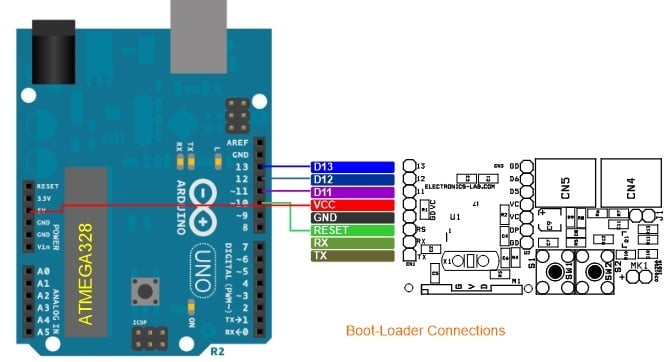
Figure 3. Bootloader connections.
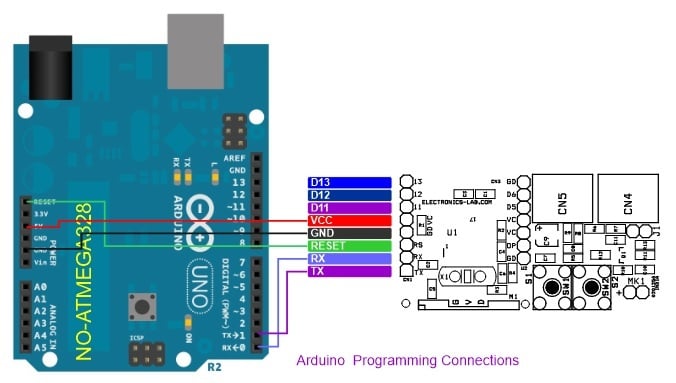
Figure 4. Arduino programming connections.
Gerber Files and Arduino Code
The PCB files for the Voice Echo are available for download here:
The Arduino code for this project can be found on CesarSound's echoTrek project page. Users may also write their own custom code for different applications. A reference for using Arduino as an ISP programmer can be found here, for example. Have fun!
All images used courtesy of Rajkumar Sharma