Facebook
 Google
 GitHub
 Linkedin
Special Diodes - Zener Diodes
Video Lectures created by Tim Feiegenbaum at North Seattle Community College.
We're in Section 9.4. We're going to be looking at special diodes. And we'll be looking at this in two sections. There are many diodes that have special properties that are useful in electronic circuits. Up till now, we've just been looking at basic diodes. And we've been using them in our rectifiers, clippers, power supplies, et cetera. A Zener diode is much like a standard diode in many respects, except that it is designed to operate in … and notice here … the reverse breakdown region of its operating curve.
All the diodes that we've been looking at up till this point, if we operate them in reverse voltage they either look like an open circuit or, if you put too much voltage across you destroy the diode. But the Zener is designed to be operated in the reverse breakdown region. And you have a … in fact, we'll be going to the simulation shortly, figure 09-31.msm.
Basic Zener Characteristics
Zener diodes are operated in their reverse breakdown mode to provide voltage regulation. And notice voltage regulation in a circuit. And voltage regulation means it is keeping a voltage at a very stable value. The point where the reverse current begins to increase is called the knee voltage. And that's going to be right here, the knee voltage right here. The current, at this point, is the knee current and you'll see this right here. And another value you have IZM. And this is the maximum allowable current. Zeners are designed for many different voltages and many different currents. And we … in this particular case, whatever this value is here … this is the voltage that this one is designed to operate at.
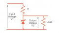
Zener Voltage Regulator
This is the circuit that we're going took at in Electronics Workbench. And what we have is here's an IN4733. If you were to look that up you would find that that is a five-volt Zener. And so the idea here is that here we have a voltage that's coming in. And this voltage may be … this is going to be … obviously, this is going to be above five volts. In fact, it must be five volts for this to work. But the Zener will begin to conduct and it's going to conduct in the reverse region and it will conduct at five volts. And regardless of what this voltage is over here, it will stay at five volts and it will make sure that a five-volt value is delivered to the load over here. And then this is a screen-saver from the simulation.
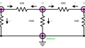
But what I want to do now is jump over to the simulation. And here is the simulation. And let's see … why don't we … here we have … let's talk about what we're doing first. Here we have a voltage source. And this voltage source is set up to supply a triangular wave into this input. And that is going to be fed to the Zener. The Zener will keep a stable voltage in spite of the fact that the input is changing radically.
Let's take a look at the inputs and outputs. Let's turn on the o-scope here. And what we will see … in fact, let's run the simulation. And you'll see here we have the triangular wave coming in. And this is … this blue line here is the output voltage. And if we go in here you'll notice we have the o-scope set up. Channel A is set to look at what is the input value. And channel B is looking at what is the voltage across the Zener. And you'll see that the input is changing quite radically. And yet the voltage across the Zener is the blue line which is very constant. And if we turn on the o-meter here, the ohmmeter is set across the load resistor in parallel with the Zener. And you see it is a very stable value right at about five volts.
Why don't we … let's pause this and let's take a closer look at our input. I'm going to scroll back to time zero on the input. And let's just take a look at what are our input values. So here we have … let's see if we can separate out our one and two … or I guess our two-way over there. If we go here to our highest point here we're going to see that we're about 11.5 volts. And then our blue line here is at about five volts.
And just as a frame of reference these one and two … if we scroll this all the way over here, you'll see we're looking at time one and time two. And they're both showing the 11.5 and the five. This is showing that in relation to time this started at zero. And so if we brought … if I just bring … let's grab two and bring it over to here and bring this one over here. And so what you'll see here is that the time … we're looking at the time between T1 and T2 is three milliseconds. The voltage at T2 we're seeing is 5.6 volts. And the blue is five.
What becomes … and it varies … the difference between T2 and T1 is 5.9 volts. So it's going from 11 and a half volts down to 5.6 volts. And they're changing constantly. And yet our output is very constant. And this is the … the purpose of a Zener diode is for voltage regulation.
Earlier we had talked about computer circuits that needed a stable DC voltage. And Zener regulators are commonly used in that application. And remember that the computer needed to have five volts. And so this could … when the AC comes in, the AC is going to have ripple in it. And it can vary from the wall. The Zener here is capable of stabilizing that value. And you can see quite clearly that here we have an input that is changing quite radically and yet the Zener is able to keep that voltage very stable.
I'm going to turn this off and jump back to our PowerPoint here. And in this first section, we just looked at Zeners as a regulating device. And we have other diodes we're going to look at in this section. But this will conclude Part A of Special Diodes.