 Facebook
 Google
 GitHub
 Linkedin
Characteristics of the Ideal Silicon Diode
In this article, we will discuss some characteristics of the ideal diode. We'll also learn how to analyze circuits that contain more than one ideal diode in conjunction with resistors and DC power sources.
In this article, we will discuss some characteristics of the ideal diode as well as learn how to analyze circuits that contain more than one ideal diode in conjunction with resistors and DC power sources.
Ideal Diode Current & Voltage Characteristics
The ideal diode might be one of the most fundamental nonlinear circuit components. The diode itself has two terminals. The symbol of the element is shown in Figure 1.1 (A).
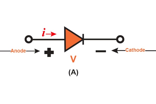
Figure 1.1 (A)
The current-voltage (i-v) properties are shown in Figure 1.1 (B).
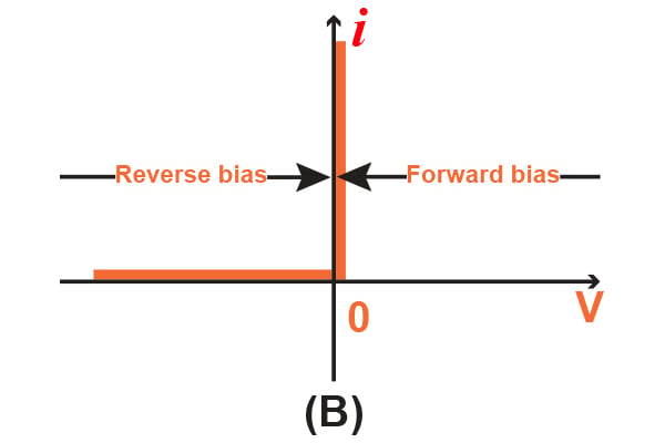
Figure 1.1 (B)
There are two important characteristics of an ideal diode: forward-biased and reverse-biased. "Reverse-biased" means that if there is a negative voltage (that is relative only to the direction of voltage flow indicated) being applied to the diode, there is no current flow and the diode acts as an open circuit, as shown in Figure 1.1 (C). An ideal diode that is reverse-biased, or operates in the reverse direction, is said to be "cut off" or just "off".
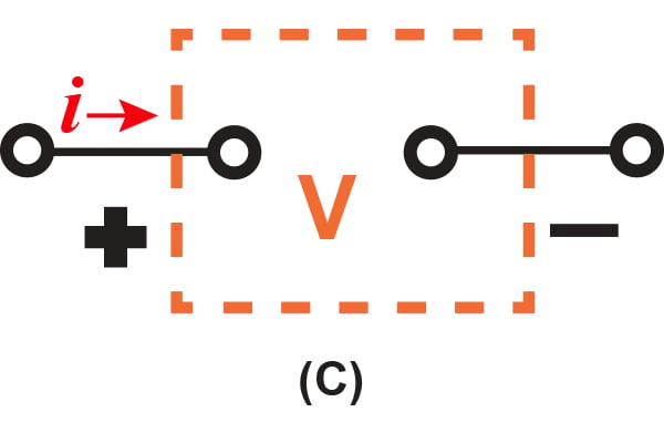
Figure 1.1 (C)
However, if there is a positive current (which is also relative to the direction of voltage flow indicated) being applied to the ideal diode, there is zero voltage drop across the diode. Simply put, the diode acts as a short circuit when operated in the forward direction and is illustrated in Figure 1.1 (D). When operated this way, the diode passes any current that has zero voltage drop. This forward-biased operation is known to be "turned on" or just "on".
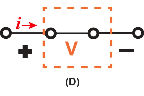
Figure 1.1 (D)
The ideal diode also refers to a diode that has a fixed, constant voltage drop. This model is very simplistic and the most widely used model in the engineering field. It is based on the fact that a diode that is said to be "forward conducting" has a voltage drop that fluctuates a small amount between around 0.6 to 0.8V. This constant voltage drop model assumes that the voltage value is at a constant 0.7V. A further article will go into this specific model in-depth.
With these descriptions of the ideal diode's characteristics, we can note that any external circuit must limit the forward current that flows through a diode, as well as the reverse voltage across a cutoff diode, to set values. In Figure 1.2, there are two diodes that represent these concepts. Looking at the diode in Figure 1.2 (A), we can see that the diode is conducting. If the diode is conducting, there will be zero voltage drop, and the current flowing through it will be set by the +20 V supply as well as the $$2 k\Omega $$ as 10 mA.
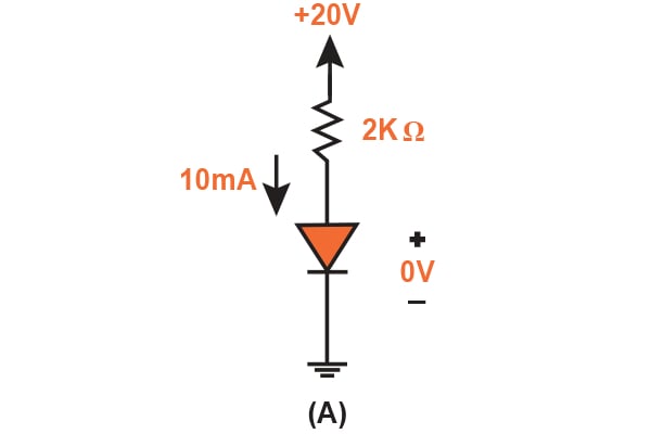
Figure 1.2 (A)
Shown in Figure 1.2 (B) is the cut-off diode, where there is zero current: Consequently, the full 20 V will appear to be reverse-bias when going across the diode.
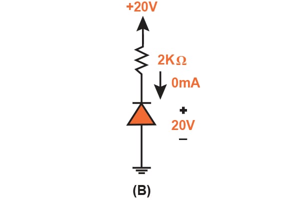
Figure 1.2 (B)
There are two terminals on the diode: positive and negative. The positive terminal is called the anode and the negative terminal is the cathode. These terms come from back when vacuum tube diodes were used. The direction of the diode symbols in Figure 1.2 (A) and Figure 1.2 (B) come from the i-v characteristic of the ideal diode, i.e., if conduction is present in one direction and not in the other.
From this characteristic of the ideal diode, we see that it is highly nonlinear. However, the diode behaves this way because the straight-line segments are at 90° to each other. This nonlinear voltage-current curve that comprises of straight-line segments is known to be "piecewise linear". Consider a device that has piecewise-linear characteristics: If it is being implemented in an application such that the voltage signal carried across the terminals swings along one way across the linear segments, then this device is considered to be a linear circuit element. However, if the voltage signal doesn't swing past one or more break points, we can no longer analyze this circuit linearly.
The Rectifier Circuit: An Application of the Diode
One of the most popular applications of the diode, the rectifier, makes use of its nonlinear i-v curve, which is illustrated in Figure 1.3 (A).
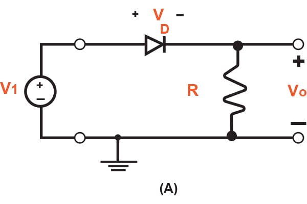
Figure 1.3 (A)
This device converts AC (which occasionally reverses its direction) to DC (that flows in one direction only). This process is known as rectification, hence the name of the device. Rectifiers can take the form of semiconductor diodes, vacuum tube diodes, and even mercury-arc valves.
The circuit itself is composed of a series connection of a diode and resistor (D and R, respectively). First, we need to let the input voltage, vl, be the sinusoidal waveform in Figure 1.3 (B) and assume that the diode is of ideal characteristics.
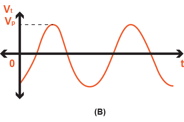
Figure 1.3 (B)
During this portion of the input sinusoid cycles (0 to vp), the positive part of vl will cause the current to flow in the forward direction through the diode. Consequently, the voltage of the diode, vD, is extremely small (ideally zero). With the diode's voltage at a value of zero, the circuit simplifies as illustrated in Figure 1.3 (C) and thus the output voltage, v0, will be equivalent to that of the input voltage.
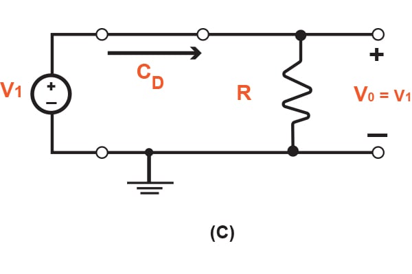
Figure 1.3 (C)
However, for the portion of the input sinusoid waveform when it is below zero, the diode will have no conductivity. Again, the circuit will simplify, which is illustrated in Figure 1.3 (D).
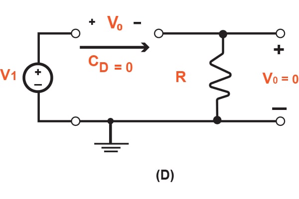
Figure 1.3 (D)
For this case, the output voltage, v0, will have a value of zero because of the lack of conductivity through the diode. With this circuit in mind, the output voltage will generate a waveform that is illustrated in Figure 1.3 (E).
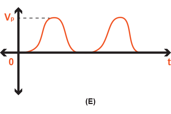
Figure 1.3 (E)
Also, there is one more point of this graph that needs noting: When vl switches polarity, v0 operates in a single direction (or unidirectional) and thus has a finite average voltage value. This finite average voltage is also known as a DC component, which is the constant voltage that is added to the pure AC waveform. Hence, the diode circuit rectifies the voltage signal, and thus is called a rectifier. This circuit is mainly used to generate a DC waveform from an AC input signal.
Conclusion
In this article, we discussed and analyzed the ideal diode circuit element. I hope that you have learned about its current and voltage characteristics as well as the rectifier circuit, which is an application of the diode. You should be able to identify two important characteristics, the forward-biased diode and the reverse-biased diode, and have an understanding of the difference between the two.
A coming article will talk more about the characteristics of the diode in terms of the terminal characteristics of junction diodes. From these characteristics, we will learn how to analyze diode circuits that operate in the forward, reverse, and breakdown bias. If you have any questions or comments, please leave them below!


Maybe I’m out of step with the times, but I thought an Ideal Diode had a zero voltage drop when forward biased? The 0.7 or whatever constant drop was an engineering approximation for silicon.