
 Facebook
 Google
 GitHub
 Linkedin
DC Electric Circuits
Intermediate Electromagnetism and Electromagnetic Induction
24 questions By Tony R. Kuphaldt
-
Question 1 of 24
As an electric current is passed through a coil of wire, it creates a magnetic field. If the magnitude of this current changes over time, so will the strength of the magnetic field.
We also know that a magnetic field flux that changes over time will induce a voltage along the length of a wire coil. Explain how the complementary principles of electromagnetism and electromagnetic induction manifest themselves simultaneously in the same wire coil to produce self-induction.
Also, explain how Lenz’s Law relates to the polarity of the coil’s self-induced voltage.
Reveal answerA changing current through a coil produces a voltage drop that opposes the direction of change.
Notes:Self-induction is not a difficult concept to grasp if one already possesses a good understanding of electromagnetism, electromagnetic induction, and Lenz’s Law. Some students may struggle understanding self-induction, because it is probably the first application they’ve seen where these three phenomena inter-relate simultaneously.
-
Question 2 of 24
∫f(x) dx Calculus alert!
In a simple resistor circuit, the current may be calculated by dividing applied voltage by resistance:

Although an analysis of this circuit probably seems trivial to you, I would like to encourage you to look at what is happening here from a fresh perspective. An important principle observed many times in the study of physics is that of equilibrium, where quantities naturally “seek” a state of balance. The balance sought by this simple circuit is equality of voltage: the voltage across the resistor must settle at the same value as the voltage output by the source:
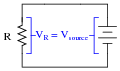
If the resistor is viewed as a source of voltage seeking equilibrium with the voltage source, then current must converge at whatever value necessary to generate the necessary balancing voltage across the resistor, according to Ohm’s Law (V = IR). In other words, the resistor’s current achieves whatever magnitude it has to in order to generate a voltage drop equal to the voltage of the source.
This may seem like a strange way of analyzing such a simple circuit, with the resistor “seeking” to generate a voltage drop equal to the source, and current “magically” assuming whatever value it must to achieve that voltage equilibrium, but it is helpful in understanding other types of circuit elements.
For example, here we have a source of DC voltage connected to a large coil of wire through a switch. Assume that the wire coil has negligible resistance (0 Ω):

Like the resistor circuit, the coil will “seek” to achieve voltage equilibrium with the voltage source once the switch is closed. However, we know that the voltage induced in a coil is not directly proportional to current as it is with a resistor - instead, a coil’s voltage drop is proportional to the rate of change of magnetic flux over time as described by Faraday’s Law of electromagnetic induction:
vcoil = N d φ dtWhere,
vcoil = Instantaneous induced voltage, in volts
N = Number of turns in wire coil \(\frac{dφ}{dt}\) = Instantaneous rate of change of magnetic flux, in webers per second
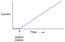
Assuming a linear relationship between coil current and magnetic flux (i.e. φ doubles when i doubles), describe this simple circuit’s current over time after the switch closes.
Reveal answerWhen the switch closes, current will steadily increase at a linear rate over time:
Challenge question: real wire coils contain electrical resistance (unless they’re made of superconducting wire, of course), and we know how voltage equilibrium occurs in resistive circuits: the current converges at a value necessary for the resistance to drop an equal amount of voltage as the source. Describe, then, what the current does in a circuit with a real wire coil, not a superconducting wire coil.
Notes:Students who do not yet understand the concept of inductance may be inclined to suggest that the current in this circuit will be infinite, following Ohm’s Law (I = E/R). One of the purposes of this question is to reveal such misunderstandings, so that they may be corrected.
This circuit provides an excellent example of the calculus principle integration, where the application of a steady voltage across the inductor results in a steadily increasing current. Whether or not you should touch on this subject depends on the mathematical aptitude of your students.
-
Question 3 of 24
A very useful method of measuring current through a wire is to measure the strength of the magnetic field around it. This type of ammeter is known as a clamp-on ammeter:
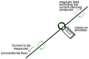
Knowing the principle behind this meter’s operation, describe what current values will be indicated by the three clamp-on ammeters in this circuit:
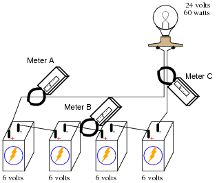
- Meter A =
- Meter B =
- Meter C =
Reveal answer- Meter A = 2.5 amps
- Meter B = 2.5 amps
- Meter C = 0 amps
Notes:Clamp-on meters are very useful pieces of test equipment, but they must be used properly. I have seen many people make the mistake of clamping one of these ammeters around multiple wires when trying to measure the amount of current through only one. If you have any clamp-on meters in your classroom, have your students set up a simple circuit like this and prove the validity of the concept.








