Kirchhoff’s Laws

DC Electric Circuits

PDF Version
  • Question 1

    Many electronic circuits use what is called a split or a dual power supply:


    Determine what a digital voltmeter would indicate if connected between the following points:

    Red lead on “A”, black lead on ground
    Red lead on “B”, black lead on ground
    Red lead on “A”, black lead on “B”
    Red lead on “B”, black lead on “A”

    NOTE: in electronic systems, “ground” is often not associated with an actual earth-soil contact. It usually only refers to a common point of reference somewhere in the circuit used to take voltage measurements. This allows us to specify voltages at single points in the circuit, with the implication that “ground” is the other point for the voltmeter to connect to.

    Reveal answer
  • Question 2

    Determine what the magnitude and polarity of the voltmeter’s indication will be in each case:
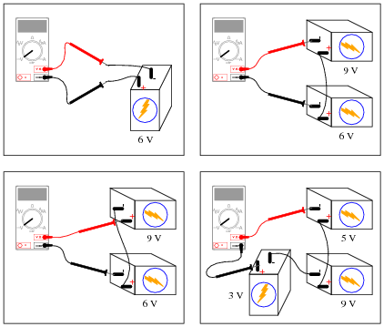


    Reveal answer
  • Question 3

    Don’t just sit there! Build something!!


    Learning to mathematically analyze circuits requires much study and practice. Typically, students practice by working through lots of sample problems and checking their answers against those provided by the textbook or the instructor. While this is good, there is a much better way.

    You will learn much more by actually building and analyzing real circuits, letting your test equipment provide the “answers” instead of a book or another person. For successful circuit-building exercises, follow these steps:

    1. Carefully measure and record all component values prior to circuit construction.
    2. Draw the schematic diagram for the circuit to be analyzed.
    3. Carefully build this circuit on a breadboard or other convenient medium.
    4. Check the accuracy of the circuit’s construction, following each wire to each connection point, and verifying these elements one-by-one on the diagram.
    5. Mathematically analyze the circuit, solving for all values of voltage, current, etc.
    6. Carefully measure those quantities, to verify the accuracy of your analysis.
    7. If there are any substantial errors (greater than a few percent), carefully check your circuit’s construction against the diagram, then carefully re-calculate the values and re-measure.

    Avoid very high and very low resistor values, to avoid measurement errors caused by meter “loading”. I recommend resistors between 1 kΩ and 100 kΩ, unless, of course, the purpose of the circuit is to illustrate the effects of meter loading!

    One way you can save time and reduce the possibility of error is to begin with a very simple circuit and incrementally add components to increase its complexity after each analysis, rather than building a whole new circuit for each practice problem. Another time-saving technique is to re-use the same components in a variety of different circuit configurations. This way, you won’t have to measure any component’s value more than once.

    Reveal answer
  • Question 4

    Suppose a technician is checking the operation of the following electronic circuit:


    She decides to measure the voltage on either side of resistor R1 with reference to ground, and obtains these readings:


    On the top side of R1, the voltage with reference to ground is -5.04 volts. On the bottom side of R1, the voltage with reference to ground is -1.87 volts. The color code of resistor R1 is Yellow, Violet, Orange, Gold. From this information, determine the following:

    Voltage across R1 (between top to bottom):
    Polarity ( and -) of voltage across R1:
    Current (magnitude) through R1:
    Direction of current through R1:

    Additionally, explain how this technician would make each one of these determinations. What rules or laws of electric circuits would she apply?

    Reveal answer
  • Question 5

    Calculate the amount of voltage between points A and B in this circuit. Be sure to identify polarity as well as magnitude:


    Reveal answer
  • Question 6

    Calculate the amount of voltage between points A and B in this circuit. Be sure to identify polarity as well as magnitude:


    Reveal answer
  • Question 7

    Determine the polarity of voltage across the resistor in this simple circuit, and be prepared to explain how you did so:


    Reveal answer
  • Question 8

    Determine the polarity of voltage across the resistor in this simple circuit, and be prepared to explain how you did so:


    Reveal answer
  • Question 9

    Determine both the polarity of voltage across the resistor in this circuit, and how much voltage will be dropped across the resistor:


    Explain the procedure(s) you used to answer both these questions.

    Reveal answer
  • Question 10

    Determine what a digital voltmeter (DVM) would indicate if connected between the following points in this circuit:


    Red lead on A, black lead on H
    Red lead on C, black lead on G
    Red lead on F, black lead on B
    Red lead on F, black lead on A
    Reveal answer
  • Question 11

    Determine what a digital voltmeter (DVM) would indicate if connected between the following points in this circuit:


    Red lead on A, black lead on H
    Red lead on C, black lead on G
    Red lead on F, black lead on B
    Red lead on F, black lead on A
    Reveal answer
  • Question 12

    A barometric altimeter is a device used to measure altitude (height) by means of atmospheric pressure. The higher you go up from sea level, the less air pressure you encounter. This decrease in air pressure is closely correlated with height, and thus can be used to infer altitude.

    This type of altimeter usually comes equipped with a “zero” adjustment, so that the instrument’s indication may be offset to compensate for changes in air pressure resulting from different weather conditions. This same “zero” adjustment may also be used to establish the altimeter’s zero indication at any arbitrary height.

    For example, if a mountain climber sets her barometric altimeter to zero meters at the base of a mountain, then climbs to the summit of that mountain (3400 meters higher than the base), the altimeter should register 3400 meters at the summit:


    While at the summit, the climber may re-set the altimeter’s “zero” adjustment to register 0 meters once again. If the climber then descends to the base of the mountain, the altimeter will register -3400 meters:


    Explain how this scenario of mountain climbing and altimeter calibration relates to the measurement of voltage between points A and B in the following circuit:


    Reveal answer
  • Question 13

    Determine the amount of voltage measured at points A and B with reference to ground, and also determine voltage VAB (defined here as the voltage indicated by a voltmeter with the red test lead touching point A and the black test lead touching point B):


    Reveal answer
  • Question 14

    A student is puzzled by a problem given by her instructor. The task is to determine the voltage VAB (defined by the instructor as the voltage indicated by a voltmeter with the red test lead touching point A and the black test lead touching point B) in this circuit:


    The student has already figured out that VA = 9 V and VB = −6 V, but does not know for certain how to calculate the voltage between points A and B. Asking her instructor for an explanation, the instructor begins to draw this illustration:


    Before the instructor begins to explain what the illustration means, however, he receives a call on his telephone and must leave the student momentarily. The student then asks you to help explain what the instructor’s illustration might mean, and how it applies to the problem of determining voltage VAB in the original circuit.

    What would your explanation be? Where do you think the instructor was going with this illustration, and how it might relate to voltages in a circuit?

    Reveal answer
  • Question 15

    Determine the voltages registered by a voltmeter between the following points in this circuit:


    VA = (red lead on A, black lead on ground)

    VB = (red lead on B, black lead on ground)

    VC = (red lead on C, black lead on ground)

    VD = (red lead on D, black lead on ground)

    VAC = (red lead on A, black lead on C)

    VDB = (red lead on D, black lead on B)

    VBA = (red lead on B, black lead on A)

    VBC = (red lead on B, black lead on C)

    VCD = (red lead on C, black lead on D)

    Reveal answer
  • Question 16

    Determine the voltages registered by a voltmeter between the following points in this circuit:


    VA = (red lead on A, black lead on ground)

    VB = (red lead on B, black lead on ground)

    VC = (red lead on C, black lead on ground)

    VD = (red lead on D, black lead on ground)

    VAC = (red lead on A, black lead on C)

    VDB = (red lead on D, black lead on B)

    VBA = (red lead on B, black lead on A)

    VBC = (red lead on B, black lead on C)

    VCD = (red lead on C, black lead on D)

    Reveal answer
  • Question 17

    Determine the voltages registered by a voltmeter between the following points in this circuit:


    VA = (red lead on A, black lead on ground)

    VB = (red lead on B, black lead on ground)

    VC = (red lead on C, black lead on ground)

    VD = (red lead on D, black lead on ground)

    VAC = (red lead on A, black lead on C)

    VDB = (red lead on D, black lead on B)

    VBA = (red lead on B, black lead on A)

    VBC = (red lead on B, black lead on C)

    VCD = (red lead on C, black lead on D)

    Reveal answer
  • Question 18

    Determine the voltages registered by a voltmeter between the following points in this circuit:


    VA = (red lead on A, black lead on ground)

    VB = (red lead on B, black lead on ground)

    VC = (red lead on C, black lead on ground)

    VD = (red lead on D, black lead on ground)

    VAC = (red lead on A, black lead on C)

    VDB = (red lead on D, black lead on B)

    VBA = (red lead on B, black lead on A)

    VBC = (red lead on B, black lead on C)

    VCD = (red lead on C, black lead on D)

    Reveal answer
  • Question 19

    Determine the voltages registered by a voltmeter between the following points in this circuit:


    VA = (red lead on A, black lead on ground)

    VB = (red lead on B, black lead on ground)

    VC = (red lead on C, black lead on ground)

    VD = (red lead on D, black lead on ground)

    VAC = (red lead on A, black lead on C)

    VDB = (red lead on D, black lead on B)

    VBA = (red lead on B, black lead on A)

    VBC = (red lead on B, black lead on C)

    VCD = (red lead on C, black lead on D)

    Reveal answer
  • Question 20

    Suppose you wanted to measure the amount of current going through resistor R2 on this printed circuit board, but did not have the luxury of breaking the circuit to do so (unsoldering one end of the resistor, detaching it from the PCB, and connecting an ammeter in series). All you can do while the circuit is powered is measure voltage with a voltmeter:


    So, you decide to touch the black probe of the voltmeter to the circuit’s “Gnd” (ground) test point, and measure the voltage with reference to ground on both sides of R2. The results are shown here:


    R2’s color code is Orange, Orange, Red, Gold. Based on this information, determine both the direction and the magnitude of DC current through resistor R2, and explain how you did so.

    Reveal answer
  • Question 21

    Shown here is a simple telegraph circuit:


    Explain why the lamps energize when either pushbutton is actuated, and why they de-energize when both pushbuttons are open (despite there being an unbroken circuit connecting both lamps and both batteries).

    Reveal answer
  • Question 22

    Imagine you are using a digital voltmeter to measure voltages between pairs of points in a circuit, following the sequence of steps shown in these diagrams:


    How much voltage would be registered by the voltmeter in each of the steps? Be sure to include the sign of the DC voltage measured (note the coloring of the voltmeter leads, with the red lead always on the first point denoted in the subscript: VBA = red lead on “B” and black lead on Ä”):

    VBA =
    VCB =
    VDC =
    VAD =

    What is the algebraic sum of these voltages?

    Reveal answer
  • Question 23

    Imagine you are using a digital voltmeter to measure voltages between pairs of points in a circuit, following the sequence of steps shown in these diagrams:


    How much voltage would be registered by the voltmeter in each of the steps? Be sure to include the sign of the DC voltage measured (note the coloring of the voltmeter leads, with the red lead always on the first point denoted in the subscript: VBA = red lead on “B” and black lead on “A”):

    VBA =
    VCA =
    VDA =
    VAA =

    Challenge question: how do these voltage measurements prove Kirchhoff’s Voltage Law, where the algebraic sum of all voltages in a loop equals 0 volts?

    Reveal answer
  • Question 24

    Identify each of the specified voltages in the following circuit. The subscripts refer to the specific test points (where the red test lead of the voltmeter touches the circuit), while ground is the point where the voltmeter’s black lead is assumed to be attached:


    For example, VB means the voltage indicated by a voltmeter with the red test lead touching point B and the black test lead touching ground.

    VA =
    VB =
    VC =
    VD =
    VE =
    Reveal answer
  • Question 25

    Use Kirchhoff’s Voltage Law to calculate the magnitude and polarity of the voltage across resistor R4 in this resistor network:


    Reveal answer
  • Question 26

    A very old but highly accurate technique for measuring voltage is to use a sensitive meter (a galvanometer) as a “balance” indicator between two voltage sources: the unknown source and a calibrated, adjustable source called the standard:


    The technique is to adjust the standard voltage source until the galvanometer registers exactly zero. When this condition is met, the system is said to be “balanced,” indicating that the two voltage sources are equal in magnitude to each other. This voltage magnitude is then read from the calibrated adjustment dial on the standard source.

    Explain how this voltage measurement technique exploits Kirchhoff’s Voltage Law, which states that the algebraic sum of all voltages in a loop must equal zero:


    EΣ(loop) = 0


    Reveal answer
  • Question 27

    Calculate the amount of voltage between test points TP1 and TP3, and also the amount of voltage between test points TP2 and TP4:


    VTP1−TP3 = VTP2−TP4 =

    Reveal answer
  • Question 28

    Imagine you are using a digital voltmeter to measure voltages between pairs of points in a circuit, following the sequence of steps shown in the following diagrams:


    How much voltage would be registered by the voltmeter in each of the steps? Be sure to include the sign of the DC voltage measured (note the coloring of the voltmeter leads, with the red lead always on the first point denoted in the subscript: VBA = red lead on “B” and black lead on “A”):

    VBA =
    VDB =
    VFD =
    VAF =

    What is the algebraic sum of these voltages?

    Reveal answer
  • Question 29

    Suppose you were measuring the voltage between “test points” TP1 and TP2 on this printed circuit board, where the circuit receives DC power from a voltage source. Suddenly, this voltage decreases. Wondering if perhaps the power supply voltage itself decreased, you go back to measure its output voltage and find that it is unchanged from before:


    Based on your knowledge of Kirchhoff’s Voltage Law, what must have happened to cause the voltage between TP1 and TP2 on the circuit board to suddenly decrease, given the power supply’s stable voltage output? Hint: the components on the circuit board are irrelevant to the answer!

    Reveal answer
  • Question 30

    When electricity and electronics students begin learning about series circuits and Kirchhoff’s Voltage Law, they are often mercilessly subjected to circuits such as this:


    A common (and legitimate!) question asked by students is, “Where would we ever encounter a circuit such as this, with batteries opposing each other?” In practice, it is rare to find electrochemical batteries intentionally connected in such a manner, with some aiding and some opposing. However, there are many practical applications where the voltages involved are not intentional, but rather are unavoidable potentials created by junctions of dissimilar materials. Take for instance the application of EKG (electrocardiogram) measurements, where metal electrodes must be placed in contact with a human body to intercept tiny voltage signals from the contracting heart muscles:


    A junction of metal wire to human skin is surprisingly complex from an electrical perspective, and may be approximately modeled by the following collection of idealized components:


    Resistors Rcontact1 and Rcontact2 represent electrical resistance between the metal electrodes and skin at the point of contact. Resistors Rtissue1 and Rtissue2 represent electrical resistance of human tissue between the points of electrode contact and the actual heart muscle. The two series-opposing potentials (E1 and E2) are not intentional, but rather the result of electrochemical action between the metal electrode surfaces and human skin. They cannot be eliminated, but their combined effect is minimal because they are approximately equal in magnitude. Explain how Kirchhoff’s Voltage Law applies to this equivalent circuit, especially how the biomedical instrument “sees” only the heart muscle voltage signal and neither of the skin-contact potentials.

    Reveal answer
  • Question 31

    How much water must flow out of the pipe with the question-mark symbols next to it?


    Explain how this hydraulic example relates to Kirchhoff’s Current Law (KCL) in an electric circuit.

    Reveal answer
  • Question 32

    In this circuit there is at least one ammeter that is not reading correctly:


    Apply Kirchhoff’s Current Law to this circuit to prove why all three current measurements shown here cannot be correct.

    Reveal answer
  • Question 33

    A voltage source is a source of electricity that (ideally) outputs a constant voltage. That is, a perfect voltage source will hold its output voltage constant regardless of the load imposed upon it:


    In real life, there is no such thing as a perfect voltage source, but sources having extremely low internal resistance come close.

    Another type of electricity source is the current source, which (ideally) outputs a constant current regardless of the load imposed upon it. A common symbol for a current source is a circle with an arrow inside (always pointing in the direction of conventional flow, not electron flow!). Another symbol is two intersecting circles, with an arrow nearby pointing in the direction of conventional flow:


    Predict how an ideal current source would behave for the following two load scenarios:


    Reveal answer
  • Question 34

    Calculate the total current output to the load resistor by this set of parallel-connected current sources:


    Also, calculate the voltage dropped across Rload.

    Reveal answer
  • Question 35

    Calculate the total current output to the load resistor by this set of parallel-connected current sources:


    Also, calculate the voltage dropped across Rload.

    Reveal answer
  • Question 36

    Use Kirchhoff’s Current Law to calculate the magnitude and direction of the current through resistor R4 in this resistor network:


    Reveal answer
  • Question 37

    Use Kirchhoff’s Current Law to calculate the magnitudes and directions of currents through all resistors in this circuit:


    Reveal answer
  • Question 38

    Predict how all component voltages and currents in this circuit will be affected as a result of the following faults. Consider each fault independently (i.e. one at a time, no multiple faults):


    Voltage source V1 fails with increased output: Solder bridge (short) across resistor R1: Solder bridge (short) across resistor R2: Resistor R3 fails open:

    For each of these conditions, explain why the resulting effects will occur.

    Reveal answer
  • Question 39

    Predict how all component voltages and currents in this circuit will be affected as a result of the following faults. Consider each fault independently (i.e. one at a time, no multiple faults):


    Current source I1 fails with increased output: Solder bridge (short) across resistor R1: Solder bridge (short) across resistor R2: Resistor R3 fails open:

    For each of these conditions, explain why the resulting effects will occur.

    Reveal answer
  • Question 40

    Predict how all component voltages and currents in this circuit will be affected as a result of the following faults. Consider each fault independently (i.e. one at a time, no multiple faults):


    Voltage source V1 fails with increased output: Resistor R1 fails open: Resistor R3 fails open: Solder bridge (short) across resistor R2:

    For each of these conditions, explain why the resulting effects will occur.

    Reveal answer
  • Question 41

    Predict how all component voltages and currents in this circuit will be affected as a result of the following faults. Consider each fault independently (i.e. one at a time, no multiple faults):


    Current source I1 fails with increased output: Resistor R1 fails open: Resistor R3 fails open: Solder bridge (short) across resistor R2:

    For each of these conditions, explain why the resulting effects will occur.

    Reveal answer
  • Question 42

    Calculate and label the currents at each node (junction point) in this circuit:


    Reveal answer
  • Question 43

    Calculate and label the currents at each node (junction point) in this circuit:


    Reveal answer
  • Question 44

    Determine the current through battery #2 in this power system, if the generator is outputting 50 amps, battery #1 is charging at a rate of 22 amps, and the light bulbs draw 5 amps of current each. Be sure to indicate whether battery #2 is charging or discharging:


    Reveal answer
  • Question 45

    Explain how an analog ammeter could be used to measure the current output of the generator in this circuit, as it charges the two batteries and energizes the three light bulbs. Be sure to connect the ammeter in the circuit in such a way that the meter needle does not drive “downscale”!


    Reveal answer
  • Question 46

    Suppose you are asked to determine whether or not each battery in this circuit is charging or discharging:


    To do so, of course, you need to determine the direction of current through each battery. Unfortunately, your multimeter does not have the current rating necessary to directly measure such large currents, and you do not have access to a clamp-on (magnetic) ammeter capable of measuring DC current.

    You are about to give up when a master technician comes along and uses her multimeter (set to measure millivolts) to take these three voltage measurements:


    “There,” she says, ït’s easy!” With that, she walks away, leaving you to figure out what those measurements mean. Determine the following:

    How these DC millivoltage measurements indicate direction of current.
    Whether or not each battery is charging or discharging.
    Whether or not these millivoltage measurements can tell you how much current is going through each battery.
    How this general principle of measurement may be extended to other practical applications.
    Reveal answer
  • Question 47

    The generator in this power system is disconnected for routine servicing by removing its fuse, leaving the two batteries to supply all power to the bank of light bulbs:


    The two batteries are rated such that they are supposed to provide at least 10 hours of back-up power in the event of a generator “outage” such as this. Unfortunately, the light bulbs begin to dim much sooner than expected. Something is wrong in the system, and you are asked to figure out what.

    Explain what steps you would take to diagnose the problem in this circuit, commenting on any relevant safety measures taken along the way.

    Reveal answer
  • Question 48

    Although the voltage divider and current divider equations are very useful in circuit analysis, they are easily confused for one another because they look so similar:


    VR = Vtotal ( R

    Rtotal
    ) Vs. IR = Itotal ( Rtotal

    R
    )


    Specifically, it is easy to forget which way the resistance fraction goes for each one. Is it [R/(Rtotal)] or is it [(Rtotal)/R] ? Simply trying to memorize which fraction form goes with which equation is a bad policy, since memorization of arbitrary forms tends to be unreliable. What is needed is recognition of some sort of principle that makes the form of each equation sensible. In other words, each equation needs to make sense why it is the way it is.

    Explain how one would be able to tell that the following equations are wrong, without referring to a book:


    VR = Vtotal ( Rtotal

    R
    ) Wrong equations! IR = Itotal ( R

    Rtotal
    )


    Reveal answer
4 Comments
  • hasan-hasanov March 13, 2022

    I think there is a mistake in question 28 more specifically step 3 and 4. I think their answers are switched. Step 3 should be 12 and Step 4 should be -24

    Like. Reply
    • D
      dalewilson March 31, 2022
      You are correct. Since Vaf spans the larger (20 KΩ) resistor, it will have a larger voltage drop than across the 10 KΩ resistor in the same loop. Thank you for bringing this to our attention.
      Like. Reply
  • C
    cranberrysky April 03, 2022

    In the notes for question 4, the diagram should have a 47k resistor, not 4.7k.

    Like. Reply