
Embedded PID Temperature Control, Part 3: Implementation and Visualization
We will implement a basic PID (proportional–integral–derivative) controller in firmware and observe the results using an oscope and LEDs.
We will implement a basic PID (proportional–integral–derivative) controller in firmware and observe the results using an oscope and LEDs.
Supporting Information
- This project makes use of a custom-designed PCB; please refer to Custom PCB Design with an EFM8 Microcontroller for guidance on incorporating EFM8 devices into your custom hardware.
- You can find a brief overview of thermocouples along with some general information about the MAX31855 in Make an EFM8-Based System for Monitoring and Analyzing Thermocouple Measurements.
- An Introduction to Control Systems: Designing a PID Controller Using MATLAB’s SISO Tool
- Negative Feedback, Part 1: General Structure and Essential Concepts
Previous Articles in This Series
- Embedded PID Temperature Control, Part 1: The Circuit
- Embedded PID Temperature Control, Part 2: Board-Level Integration
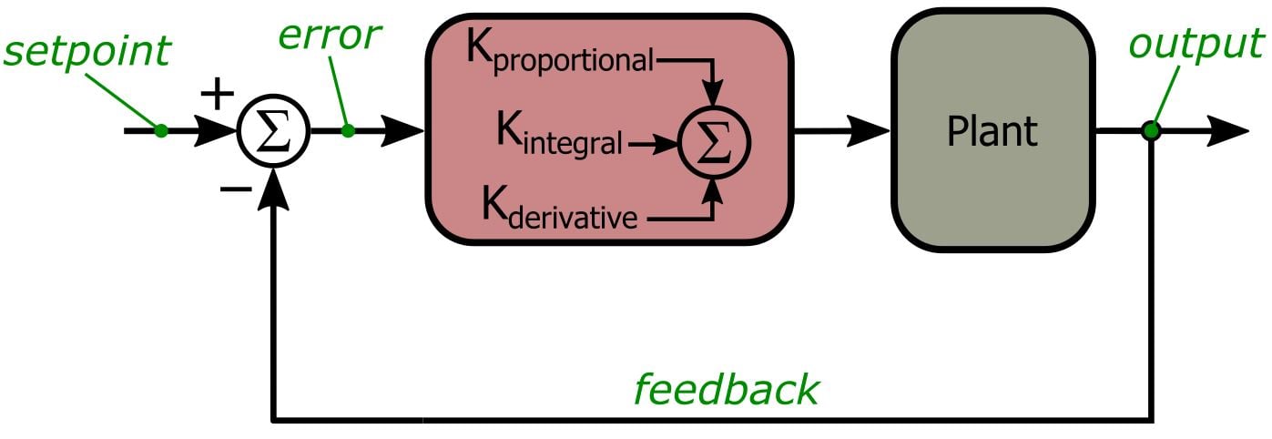
Before we get started, here is the PID control system diagram presented previously:
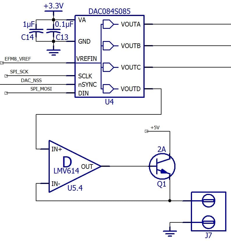
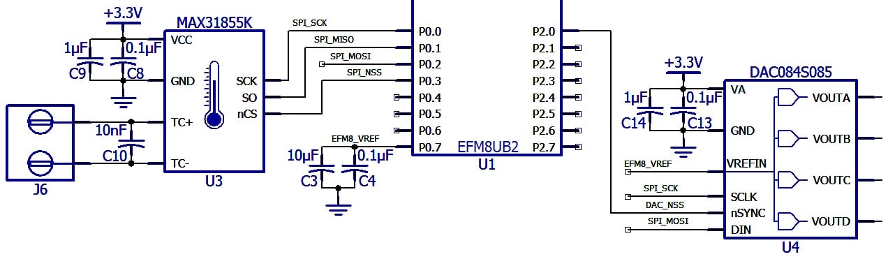
And here are PID-related portions of the schematic:
The PID Procedure
In the first article we looked at the circuit used to drive relatively large amounts of current through the heating-element resistor, and in the second article we discussed timing details and firmware related to the SPI interface that allows us to integrate the three primary components of our PID system. Now we are ready to implement a basic PID control routine. This is the general procedure that we will translate into EFM8 code:
- Choose values for the proportional, integral, and derivative gain.
- Clear variables that should start at zero, namely, the accumulated error used with the integral gain and the previous error value used with the derivative gain.
- Gather data from the MAX31855 and convert it to a temperature value (in Celsius).
- Calculate the current error by subtracting the measured temperature from the setpoint temperature.
- Add the current error to the accumulated error used with the integral gain.
- Calculate the rate of change of the error (used with the derivative gain) by subtracting the previous error from the current error.
- Update the previous error (for use in the next iteration) by setting the previous error equal to the current error.
- Calculate the PID control output by multiplying the P gain by the current error, the I gain by the accumulated error, and the D gain by the rate of change of the error, and then adding up the results of these three multiplications.
- Constrain the PID control output according to an acceptable range. Our current-drive circuitry can only source about 1 A, and we can’t go below zero current. (Remember that in this system we can only generate heat; we can’t remove heat. Thus, PID output values below zero have no physical meaning. This would not be the case if, for example, we were working with an environmental control system that had both a heater and an air conditioner. In that case, a negative PID output would tell the system to completely deactivate the heater and then activate the air conditioner.)
- Apply the PID control output (in our case this means writing a new value to the DAC channel that controls the heater-drive voltage).
- Wait until the current PID interval has expired before starting the next iteration.
What Happened to Time?
One thing you may have noticed in the above procedure is that we do not incorporate a time quantity when we integrate and differentiate the error. In a continuous-time representation, the error is differentiated with respect to time and integrated with respect to time. In our discrete-time implementation, though, we don’t need to explicitly account for the incremental time dt because our PID interval is constant and we calculate the integral and derivative error during every iteration. For example, the purpose of the derivative error is to tell us how quickly (and in what direction, positive or negative) the measured temperature is changing. By simply subtracting the previous error from the current error, we can determine how much the temperature changed during the previous PID interval. The next derivative error will tell us how much the temperature changed during the succeeding PID interval, and so forth. Thus, the quantity dt is effectively included in the calculation—one derivate error can be directly compared to all the others because they are calculated with reference to the same time interval.
Visualization
Unless you’re the sort of person who can look at something and determine its exact temperature, you won’t know what your PID controller is doing without some way of visualizing the changes in the system. For this stage of the project, we will assess our PID functionality in two ways: 1) by using an oscope to display the voltage applied to the heating-element resistor, and 2) by increasing the brightness of an LED as the measured temperature approaches the setpoint temperature. We will make the LED technique a little more informative by also turning on a second LED when the measured temperature equals (or exceeds) the setpoint temperature.
The PCB we are using for this project includes an RGB LED module along with circuitry that allows us to precisely control the brightness of each LED via DAC outputs (for more information on this functionality, refer to Design a Color Sensor with Measurements Displayed via an RGB LED Module). We will use the red LED to represent the change in temperature and the green LED to indicate that the measured temperature has reached the setpoint.
There are different ways you could convey temperature information via LED brightness. Our approach will be the following: When we first activate the PID controller, we store the difference between the current measured temperature and the setpoint as Initial_Error. During each iteration we calculate 1 minus the ratio of the current error to the initial error, and then we scale the result of this subtraction according to a predetermined 8-bit DAC value:
\[DAC\ value=\left(1-\frac{current\ error}{initial\ error}\right)\times DAC\ value\ for\ optimal\ brightness\]
So when the PID controller first starts up, (1 – (current error)/(initial error)) will be near zero and the LED will be off. As the measured temperature increases, the current error will decrease and thus (1 – (current error)/(initial error)) will increase toward 1, and consequently the DAC value will increase toward the “DAC value for optimal brightness.” I chose 100 as the optimal-brightness value because I don’t like staring at these LEDs when they’re cranked up all the way to the full 20 mA (a DAC value of 255 corresponds to 20 mA, so 100 is about 8 mA).
This is the code that accomplishes the LED functionality.
/*-----This section executes before the main while loop.-----*/
/*-----------------------------------------------------------*/
GatherMAX31855Data();
while(TEMP_DATA_READY == FALSE);	//wait until the SPI transaction is complete

Measured_Temp = ConvertMAX31855Data_to_TempC();

//the initial error is needed only for the LED functionality
Initial_Error = Setpoint_Temp - Measured_Temp;
/*-----------------------------------------------------------*/


/*-----This section is included in the while loop.-----*/
/*-----------------------------------------------------*/
/*The red LED stays off if for some reason the current
 * error exceeds the initial error.*/
if(Error > Initial_Error)
	LED_Temp_Indicator = 0;
/*This calculation is explained in the article.*/
else
	LED_Temp_Indicator = (1 - (Error/Initial_Error)) * 100;

/*Here we turn on the green LED if we have
 * reached the setpoint. Notice that there
 * is no code that sets the green LED's DAC
 * value back to zero. This means that once
 * the green LED is on, it stays on.*/
if(Measured_Temp >= Setpoint_Temp)
	LED_Setpoint_Reached = 100;

UpdateDAC(DAC_RGB_R, LED_Temp_Indicator);
UpdateDAC(DAC_RGB_G, LED_Setpoint_Reached);
/*-----------------------------------------------------*/
Firmware
Here is the PID code (including the code for controlling the LEDs). The comments and descriptive identifiers should make everything pretty clear. Note that the PID control output is limited to 200. We can go as high as 255, but the full heater current is not needed for merely demonstrating functionality.
Setpoint_Temp = 50;

K_proportional = 40;
K_integral = 10;
K_derivative = 0;

Error_Integral = 0;
Previous_Error = 0;

/*Apparently the MAX31855 generates better
 * temperature data if it has a little extra time
 * after power-up. This is why we have a 1-second
 * delay here.*/
Delay_10ms(100);

GatherMAX31855Data();
while(TEMP_DATA_READY == FALSE);	//wait until the SPI transaction is complete

Measured_Temp = ConvertMAX31855Data_to_TempC();

//the initial error is needed only for the LED functionality
Initial_Error = Setpoint_Temp - Measured_Temp;

while (1)
{
	GatherMAX31855Data();
	while(TEMP_DATA_READY == FALSE);	//wait until the SPI transaction is complete

	Measured_Temp = ConvertMAX31855Data_to_TempC();

	Error = Setpoint_Temp - Measured_Temp;

	/*We don't want the integral error to get
	 * way too large. This is a standard problem
	 * referred to as integral windup. One solution
	 * is to simply restrict the integral error to
	 * reasonable values.*/
	Error_Integral = Error_Integral + Error;
	if(Error_Integral > 50)
		Error_Integral = 50;
	else if(Error_Integral < -50)
		Error_Integral = -50;

	Error_Derivative = Error - Previous_Error;
	Previous_Error = Error;

	PID_Output = (K_proportional*Error) + (K_integral*Error_Integral) + (K_derivative*Error_Derivative);

	/*We need to restrict the PID output to
	 * acceptable values. Here we have limited it
	 * to a maximum of 200, which corresponds
	 * to about 780 mA of heater-drive current, and
	 * a minimum of 0, because we cannot drive
	 * less than 0 A through the heating
	 * element.*/
	if(PID_Output > 200)
		PID_Output = 200;
	else if(PID_Output < 0)
		PID_Output = 0;

	//here we convert the PID output from a float to an unsigned char
	Heater_Drive = PID_Output;

	UpdateDAC(DAC_HEATER, Heater_Drive);

	/*The red LED stays off if for some reason the current
	 * error exceeds the initial error.*/
	if(Error > Initial_Error)
		LED_Temp_Indicator = 0;
	/*This calculation is explained in the article.*/
	else
		LED_Temp_Indicator = (1 - (Error/Initial_Error)) * 100;

	/*Here we turn on the green LED if we have
	 * reached the setpoint. Notice that there
	 * is no code that sets the green LED's DAC
	 * value back to zero. This means that once
	 * the green LED is on, it stays on.*/
	if(Measured_Temp >= Setpoint_Temp)
		LED_Setpoint_Reached = 100;

	UpdateDAC(DAC_RGB_R, LED_Temp_Indicator);
	UpdateDAC(DAC_RGB_G, LED_Setpoint_Reached);

	/*Here we wait until the PID interval has expired,
	 * then we begin a new iteration. The interval is
	 * currently set to 1 second.*/
	PID_WAIT = TRUE;
	while(PID_WAIT == TRUE);
}
Here is a link to download all the source and project files.
PIDTemperatureControl_Part3.zip
Results
The following two videos give you an idea of how the system works. We’ll talk more about tuning—i.e., properly choosing the proportional, integral, and derivative gain—in future articles. For now, we will simply look at the results for a proportional-only system and a proportional-integral (i.e., no derivative) system. The proportional gain is set to 40 and the integral gain to 10 (these values are based primarily on basic consideration of the system characteristics, though I tweaked the proportional gain based on empirical observations).
This first video shows the P-only system taking the temperature from about 30°C to a setpoint of 50°C. First, the scope trace increases to the maximum drive voltage, then you notice the red LED becoming gradually brighter as the measured temperature increases. The drive voltage eventually decreases as the measured temperature gets close to the setpoint. However, the green LED never turns on, and then the drive voltage begins to increase again. This system tends to remain a few degrees below the setpoint; this steady-state error is a common disadvantage of P-only systems. (Note that the video runs at 4x normal speed.)
Reaching the setpoint is indicated by the green LED, but with the P-only system, the measured temperature tends to remain a few degrees below the setpoint. Thus, the green LED never turns on.
Now we introduce some integral gain to reduce the steady-state error. This PI system is performing the same control task, i.e., taking the temperature from 30°C to a setpoint of 50°C. The drive voltage initially increases to max and the red LED becomes gradually brighter, as in the first video, but then the green LED turns on, indicating that we reached the setpoint. The integral error does not immediately decrease to zero, so the drive voltage remains at maximum for a while; during this time the measured temperature is above the setpoint. Eventually, the integral error “unwinds” enough to cause the drive voltage to decrease. (Note that the video runs at 4x normal speed.)
We can introduce integral gain to reduce the steady-state error. With the PI system, the green LED turns on, indicating that we reached the setpoint.
Next Article in Series: Embedded PID Temperature Control, Part 4: The Scilab GUI


It is the project that I looked for.
Thank you very much.
Hi Robert, firstly congratulations for all the great articles.
I am currently working in LED lamp and we would like to implement a real-time temperature control. The LED lamp is controlled by PWM and a micro controller, so we can adjust the power as you do in this example. My doubts:
1/ We do not have to reach a target temperature, but limiting the temperature to protect the user and electronics. We can do it by progressively dimming the LEDs intensity when it approach or pass the temperature limit. Is your model still valid for this operation mode or do we need to change something?
2/ The power of the lamp can be adjusted by the user and we plan to adjust the gains modelling the system with a 50% step input (at 100% the lamp may get too hot). Will the PID work well when the lamp is operated at different power values? Or do we need to consider it in the design somehow?
Beside the questions above we would really appreciate a guide or advice on the required steps.
Thank you very much.
Pedro