Facebook
 Google
 GitHub
 Linkedin
Digital Circuits
Electromechanical Relay Logic
19 questions By Tony R. Kuphaldt
-
Question 1 of 19
In ladder logic symbolism, an electromechanical relay coil is shown as a circle, and the contact(s) actuated by the coil as two parallel lines, almost like a capacitor symbol. Given this knowledge, interpret the following ladder logic diagram:

How do we know which relay contact is actuated by which relay coil? How does this convention differ from that of standard electrical/electronic schematic diagrams, where the relay coil is shown as an actual coil of wire (inductor symbol) with the contact “linked” to the coil by a dashed line? Also, what type of logic function behavior (AND, OR, NAND, or NOR) does the above circuit exhibit?
Reveal answerIn ladder logic diagrams, relay coils are associated with their respective contacts by name rather than by proximity. In this particular circuit, the logic function represented is the AND function.
Notes:Many students find it confusing that relay contacts and coils need not be drawn next to one another in a ladder logic diagram, because it is so different from the schematic diagrams they are accustomed to. The non-necessity of proximity in a ladder logic diagram does have its advantages, though! It is simply a matter of getting used to a new way of drawing things.
-
Question 2 of 19
There is a problem somewhere in this relay logic circuit. Lamp 2 operates exactly as it should, but lamp 1 never turns on. Identify all possible failures in the circuit that could cause this problem, and then explain how you would troubleshoot the problem as efficiently as possible (taking the least amount of electrical measurements to identify the specific problem).

Reveal answerThis is a problem worthy of a good in-class discussion with your peers! Of course, several things could be wrong in this circuit to cause lamp 1 to never energize. When you explain what measurements you would take in isolating the problem, be sure to describe whether or not you are actuating either of the pushbutton switches when you take those measurements.
Notes:Be sure to leave plenty of classroom time for a discussion on troubleshooting this circuit. Electrical troubleshooting is a difficult-to-develop skill, and it takes lots of time for some people to acquire. Being one of the most valuable skills a technical person can possess, it is well worth the time invested!
The challenge question is very practical. Too many times I have seen students take meter measurements when their other senses provide enough data to render that step unnecessary. While there is nothing wrong with using your meter to confirm a suspicion, the best troubleshooters use all their senses (safely, of course) in the isolation of system faults.
-
Question 3 of 19
A very common application of electromechanical relay logic is motor control circuitry. Here is a ladder diagram for a simple DC motor control, where a momentary pushbutton switch starts the motor, and another pushbutton switch stops the motor:

Translate this ladder diagram into point-to-point connections between the following components (shown in the following illustration):

Reveal answerThe wiring sequence shown here is not the only valid solution to this problem!
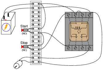
Notes:This circuit provides students with an opportunity to analyze a simple latch: a system that “remembers” prior switch actuations by holding a “state” (either set or reset; latched or unlatched). A simple motor start/stop circuit such as this is about as simple as latch circuits get.
Students should be able to immediately comprehend the benefit of using nice, neat, structured ladder diagrams when they see the tangled mess of wires in a real motor control circuit. And this is not even a complex motor control circuit! It takes very little imagination to think of something even uglier than this, and what a task it would be to troubleshoot such a circuit without the benefit of a ladder diagram for guidance.