 Facebook
 Google
 GitHub
 Linkedin
Single-ended and Differential Amplifiers
For ease of drawing complex circuit diagrams, electronic amplifiers are often symbolized by a simple triangle shape, where the internal components are not individually represented. This symbology is very handy for cases where an amplifier’s construction is irrelevant to the greater function of the overall circuit, and it is worthy of familiarization:
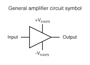
The +V and -V connections denote the positive and negative sides of the DC power supply, respectively. The input and output voltage connections are shown as single conductors, because it is assumed that all signal voltages are referenced to a common connection in the circuit called ground. Often (but not always!), one pole of the DC power supply, either positive or negative, is that ground reference point. A practical amplifier circuit (showing the input voltage source, load resistance, and power supply) might look like this:
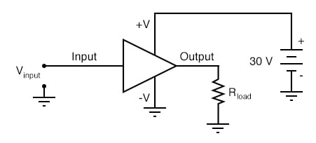
Amplifier Circuit’s Function
Without having to analyze the actual transistor design of the amplifier, you can readily discern the whole circuit’s function: to take an input signal (Vin), amplify it, and drive a load resistance (Rload). To complete the above schematic, it would be good to specify the gains of that amplifier (AV, AI, AP) and the Q (bias) point for any needed mathematical analysis.
If it is necessary for an amplifier to be able to output true AC voltage (reversing polarity) to the load, a split DC power supply may be used, whereby the ground point is electrically “centered” between +V and -V. Sometimes the split power supply configuration is referred to as a dual power supply.
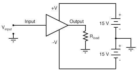
The amplifier is still being supplied with 30 volts overall, but with the split voltage DC power supply, the output voltage across the load resistor can now swing from a theoretical maximum of +15 volts to -15 volts, instead of +30 volts to 0 volts. This is an easy way to get true alternating current (AC) output from an amplifier without resorting to capacitive or inductive (transformer) coupling on the output. The peak-to-peak amplitude of this amplifier’s output between cutoff and saturation remains unchanged.
Differential Amplifier
By signifying a transistor amplifier within a larger circuit with a triangle symbol, we ease the task of studying and analyzing more complex amplifiers and circuits. One of these more complex amplifier types that we’ll be studying is called the differential amplifier. Unlike normal amplifiers, which amplify a single input signal (often called single-ended amplifiers), differential amplifiers amplify the voltage difference between two input signals. Using the simplified triangle amplifier symbol, a differential amplifier looks like this:
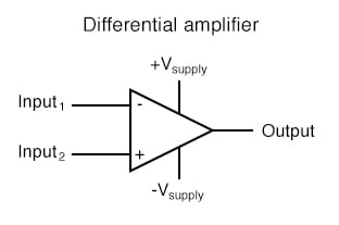
The two input leads can be seen on the left-hand side of the triangular amplifier symbol, the output lead on the right-hand side, and the +V and -V power supply leads on top and bottom. As with the other example, all voltages are referenced to the circuit’s ground point. Notice that one input lead is marked with a (-) and the other is marked with a (+). Because a differential amplifier amplifies the difference in voltage between the two inputs, each input influences the output voltage in opposite ways. Consider the following table of input/output voltages for a differential amplifier with a voltage gain of 4:
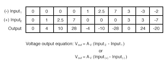
An increasingly positive voltage on the (+) input tends to drive the output voltage more positive, and an increasingly positive voltage on the (-) input tends to drive the output voltage more negative. Likewise, an increasingly negative voltage on the (+) input tends to drive the output negative as well, and an increasingly negative voltage on the (-) input does just the opposite. Because of this relationship between inputs and polarities, the (-) input is commonly referred to as the inverting input and the (+) as the noninverting input. It may be helpful to think of a differential amplifier as a variable voltage source controlled by a sensitive voltmeter, as such:
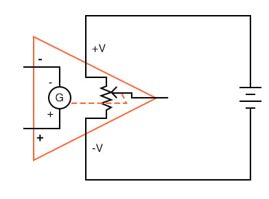
Bear in mind that the above illustration is only a model to aid in understanding the behavior of a differential amplifier. It is not a realistic schematic of its actual design. The “G” symbol represents a galvanometer, a sensitive voltmeter movement. The potentiometer connected between +V and -V provides a variable voltage at the output pin (with reference to one side of the DC power supply), that variable voltage set by the reading of the galvanometer. It must be understood that any load powered by the output of a differential amplifier gets its current from the DC power source (battery), not the input signal. The input signal (to the galvanometer) merely controls the output. This concept may at first be confusing to students new to amplifiers. With all these polarities and polarity markings (- and +) around, it’s easy to get confused and not know what the output of a differential amplifier will be. To address this potential confusion, here’s a simple rule to remember:
Relationship of Input and Output Polarity
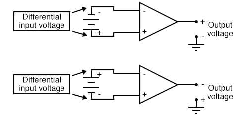
When the polarity of the differential voltage matches the markings for inverting and noninverting inputs, the output will be positive. When the polarity of the differential voltage clashes with the input markings, the output will be negative. This bears some similarity to the mathematical sign displayed by digital voltmeters based on input voltage polarity. The red test lead of the voltmeter (often called the “positive” lead because of the color red’s popular association with the positive side of a power supply in electronic wiring) is more positive than the black, the meter will display a positive voltage figure, and vice versa:
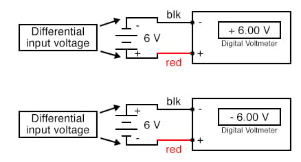
Just as a voltmeter will only display the voltage between its two test leads, an ideal differential amplifier only amplifies the potential difference between its two input connections, not the voltage between any one of those connections and ground. The output polarity of a differential amplifier, just like the signed indication of a digital voltmeter, depends on the relative polarities of the differential voltage between the two input connections.
Uses of Differential Amplifier
If the input voltages to this amplifier represented mathematical quantities (as is the case within analog computer circuitry), or physical process measurements (as is the case within analog electronic instrumentation circuitry), you can see how a device such as a differential amplifier could be very useful. We could use it to compare two quantities to see which is greater (by the polarity of the output voltage), or perhaps we could compare the difference between two quantities (such as the level of liquid in two tanks) and flag an alarm (based on the absolute value of the amplifier output) if the difference became too great. In basic automatic control circuitry, the quantity being controlled (called the process variable) is compared with a target value (called the setpoint), and decisions are made as to how to act based on the discrepancy between these two values. The first step in electronically controlling such a scheme is to amplify the difference between the process variable and the setpoint with a differential amplifier. In simple controller designs, the output of this differential amplifier can be directly utilized to drive the final control element (such as a valve) and keep the process reasonably close to setpoint.
REVIEW:
- A “shorthand” symbol for an electronic amplifier is a triangle, the wide end signifying the input side and the narrow end signifying the output. Power supply lines are often omitted in the drawing for simplicity.
- To facilitate true AC output from an amplifier, we can use what is called a split or dual power supply, with two DC voltage sources connected in series with the middle point grounded, giving a positive voltage to ground (+V) and a negative voltage to ground (-V). Split power supplies like this are frequently used in differential amplifier circuits.
- Most amplifiers have one input and one output. Differential amplifiers have two inputs and one output, the output signal being proportional to the difference in signals between the two inputs.
- The voltage output of a differential amplifier is determined by the following equation: Vout = AV(Vnoninv - Vinv)
RELATED WORKSHEET:


Can I use non inverting input of a precision unity gain differential amplifier into a 300V DC voltage divider (at 4 V) and set inverting input to ground, and then use the output into a atmega328p/arduino nano/uno analog input for measurement?