Facebook
 Google
 GitHub
 Linkedin
Op Amps Characteristics (Part 4) - Common vs. Differential
Video Lectures created by Tim Feiegenbaum at North Seattle Community College.
We're concluding Section 11.1. We start out with a discussion of common-mode versus differential-mode gain.
Differential-load voltage gain is the gain given to a voltage that appears between the two input terminals. It represents two different voltages on the inputs. Recall that a differential amplifier amplifies the difference and with an operational amp, the input stage is a differential amp so it will amplify the difference between the two voltages on the two inputs.
By contrast, common-load voltage gain is the gain given to a voltage that appears on both input terminals with respect to ground. This it the same input on both terminals and we mentioned this back in Chapter 10, actually.
Ideally, an op amp will reject voltages that appear on both input terminals, resulting in common-mode voltage gain of zero. In our previous discussions of this, this was how an op amp managed to reject most noise inputs because most noise will appear on both appear on both terminals and since it is the same value on both inputs, it will not get amplified. So op amps are famous in one regard because of this because they virtually, I shouldn't say they eliminate noise, but they severely reduce the amount of noise.
Frequency Response
An ideal op amp has infinite voltage gain over an infinite range of frequencies.
An op amp will also respond to very low frequency down to dc.
In practical op amps, voltage gain decreases as frequency increases. Though this is an ideal concept, here, reality is in practical op amps, voltage gain decreases as frequency increases.
By adding external circuitry, the closed-loop voltage gain can be decreased to a practical value that is constant over a wide range of frequencies. This has to do with negative feedback.
Here we have a graph and we're looking at open-loop voltage gain versus frequency. Here we have this graph, along with the bottom you will see frequencies and they go from 1 up to about 1 meg right here. Then along the edge, we see the gain and the gain is given in decibels. If we want to put a little bit of … Notice here we have a gain of 100, if we grabbed our calculator, maybe we can do a little bit of conversion here to put these into … If you're very comfortable with decibels …
Let's convert a few of these to values of A. Here is the formula: If, we were looking at, for example, a decibel value of 100 and we wanted to convert it to regular A, we would take the antilog of 100 divided by 20. Let's do that. If we said 100 divided by 20 and then we wanted to take the antilog of that, there's our log right there so you go to shift and this is actually the antilog right here. There we have it, 100 exponents 3, that would equate to a gain of 100,000.
Let's do just a couple more. If we had, let's look at the one for 40. If we took 40 and we divided that by 20 and then if we took the antilog of that value, we would find that that is 100. That would be 100.
Let's look at one more. Let's look at 20 decibels. If you took 20 divided by 20, that's going to be 1. Then if we took the antilog of that, that would be a gain of 10. At 20, we would see a gain of 10.
What we'll note here, this is the gain relationships and frequency that we would see of an op amp and this is peculiar to the 741 op amp. This will vary depending on the op amp and there are literally thousands of op amps so there'd be lots of different curves. This is a very popular op amp that's widely used, and let's look at the characteristics of this device.
First of all, we'll note that here we have a gain of 100,000, but note the frequency. Here we are at 100,000 but that is only up to 10 hertz. We have this phenomenal gain of 100,000 but the frequency only goes up to 10 hertz, which isn't terribly significant.
Let's drop down here, let's go down to this other … We said at 40 decibels this would be a gain of 100 and let's stretch out over here and at 100 we would get up to 10K hertz. Notice we've got 10K hertz of bandwidth, but our gain has been reduced down to 100. This is where we would use the negative feedback so that we could get a very stable gain but we could also get a much wider frequency. At a gain of 10, our frequency range would go all the way out to 100K.
If we continue down this slope, here, and if we get down to zero, at zero dB, the gain A equals 1. If we go over here we'll find out that that is at 1 megahertz. There is a term they use in op amp that's called F-Unity and in this case, for the 741, it will be 1 megahertz and F-Unity, Unity is for 1, so the frequency where gain equals 1 would be 1 megahertz.
Though not mentioned in your text, it's kind of interesting to observe, and this is just an observation, that the amplitude decreases at the rate of 20 dB per decade of frequency. If you look at this, you'll notice here we go from 100 down to 80, from here to here, and notice the frequency's one decade from 10 to 100, and then from 80 to 60, the next one is from 100 to 1K, and then from 1K to 10K, again, it drops 20, and that will be across the entire range. Usually what you will see in op amp behavior is the amplitude and the frequency will be separated by 20 dB per decade.
Output Slew Rate
The maximum output voltage swing of an op amp is limited to the maximum values of the source voltage and the internal design of the op amp. Many op amps have differing internal designs.
The output voltage swing is also limited regarding how fast it can change.
The maximum rate of change of the output voltage is called the slew rate of the op amp.
Slew rate is specified in volts per second or volts per microsecond. How many volts can it change in 1 microsecond of time?
The 741 has a slew rate of .5 volts per microsecond. Others that support very high frequencies can go up as high as 5500 volts per microsecond.
This limitation is designed into the op amp to prevent unwanted high-frequency oscillation.
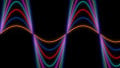
This is actually a screenshot from Multisim and the input signal you see here is the nice sine wave here and this is the output. This output is displaying slew rate distortion. The output should look like the input but the amplitude and frequency is such that the output cannot keep up with the input.
The basic idea is that if we had … Let's say here we have a nice AC input coming in and this would be the input to our op amp. The output of the op amp wants to go to this particular speed of change but it is limited to changing, it's the 741, to .5 volts per microsecond. What will happen is it will attempt to keep up with this rate of change but it can only go, for example, this fast. It can't keep up with this rate of change and so it ends up coming down like this and it wants to keep up with this rate of change, can't do it, and so it ends up looking something like that.
Slew rate distortion is a function not only of frequency but also of amplitude. If, for example, the input signal had been kind of like this, if it had been at a lower amplitude and the same frequency, the op amp could have kept up with that rate of change, but this rate of change was just too severe.
This particular aspect of an op amp, the reason that does this is that there's a design built into op amps to prevent high-frequency oscillations. There was a little component, some of you may recall, at the beginning of this chapter, when we were looking at the schematic design of an op amp, I circled a little capacitor and that capacitor is actually referred to as a compensating capacitor and it is the component that establishes this value.
The reason this is desirable is that this compensating cap will cause the 741, for example, with this relatively slow rate of slew rate, to have very few high-frequency oscillations. In this particular device, though, it supports very high frequency, it'll have lots of oscillations and those oscillations will have to be dealt with.
In this section, we looked at output slew rate, we looked at a graph and we looked at the gain in relationship to the frequency and we found out that the more gain that we got the less frequency response and if we wanted to get a wider range of frequencies we had to reduce our gain. We also looked at common-mode versus differential-mode gain and we recalled that with differential-mode gain the op amp amplifies the difference and with common-mode, it hopefully doesn't amplify anything because if you have the same input on both inputs you won't get an output with an op amp.
This concludes section 11.1.
Related Content