Facebook
 Google
 GitHub
 Linkedin
Basic Amplifier Configuration (Part 2) - Inverting Amplifier
Video Lectures created by Tim Feiegenbaum at North Seattle Community College.
Continuing with the second half of 11.2, we're looking at the inverting amplifier circuit. First of all, circuit identification, Rf provides a portion of the output back to the input and this is in the form of negative feedback. Rf is one way of identifying an inverting amplifier. The input signal is applied to the inverting input, which results in the output being inverted. Circuit operation; because the minus input remains at ground potential, zero volts, it is referred to as a, and we've talked about this before, virtual ground. Because of the feedback loop, voltage gain, in an inverting amplifier, is minus Rf divided by R1. The voltage gain is going to … the minus indicates that it is inverted. Again, we mention here Rb's only purpose is to offset input offset current and effectively no voltage drops so we can ignore Rb.
The virtual ground concept; the difference between the inputs is zero volts. OK? The difference between the inputs is zero volts. Non-reverting input is at ground so inverting input is virtually at ground. Since this can be ignored, and since we have the concept here of a connection between here and here, then the input is at what we would call a virtual ground. This voltage will appear across this vector, we could calculate the current that will flow through here, and since no current flows into the Op-Amp, that same current will flow through Rf. We can calculate the output voltage that way, and we will in just a moment. Since no current flows into the Op-Amp, the same current flows to Rf; just add that and then here is our gain ratio. Let's calculate our gain; we say that is going to be Rf over R1 and it will be minus. In this case, we have 56 divided by … what? 2.7 and that will give us our gain relationship. Let's see if we can take a quick look at that. If we say 56 divided by … and that is 2.7 … 2.7 equals and we have 20.741...so 20.741, that will be our gain ratio.
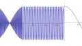
Now again, we can calculate using Ohm's Law and in this case, we could say 0.1 volts divided by 2.7 K will yield a current. That current will be felt through this component and the voltage across this component will be our output, it won't be our 1+Rf, it will simplify be Rf because we have that virtual ground concept here so our output will be from here to here so, whatever that currently is will take that current times the value of Rf and we should get our output, so let's pull up our calculator again and before we do this, why don't we look at … let's see … we've got 20.741 on the screen. If we took that … times the 0.1, that will yield 2.074 volts … we write down … 2.074 volts … now that is just the calculation based on the ratio of Rf to R1 times the input voltage. Now if we did the Ohm's Law calculation here, let's go in and say we have 0.1 volts as our input and we're dividing that by 2.7 K … 2.7 exponent three … and that would yield this current. Remember that current will be felt through this, through the 56K, so we would take that … times 56 exponent three, and there we have exactly the same value; 2.074 volts. Again, here is the same circuit and just as a review: again A equals Rf over R1, and that was a negative value … and that was about it for that particular circuit. This is a simulation from Workbench. Let's see … this is a little bit difference. This is the way it looks at Workbench. Here is our non-inverting input with Rb there. Here is our inverting input coming in. Let's see … it is across here we have Rf is 47 K and the R1 is 3.9 K and our input is 25 millivolts, so why don't pull up our calculator and see what this would result in, so we have 47 divided by 3.9 … and that will equal 12.451 and our input is 25 millivolts, we'll take that times 25 exponent minus three … and that will give up 301 milliamps. Now, this is a screen shot of the oscilloscope in Electronics Workbench, and I'm going to put a negative value right here. That was … what was that value? 301 … I forgot to write that down. It was in fact 301.2 millivolts. If we look on our screenshot here, the red value is the input, the blue is the output, and this yellow stripe here indicates the peak of the blue and you'll notice here that there are 301 milliamps that are exactly what we had calculated.
The red here is 24.988 that is very close to being the 25 millivolts that is applied to the input. That is our output for our amplifier it was the inverting input. I'm going to minimize this … and that concludes this section. Let's see, just quickly by review, we were looking at the inverting amp, we looked at the gain. Remember that the gain will be inverted … that negative there Rf over R1. We did the calculations. That concludes section 11.2.
Related Content