 Facebook
 Google
 GitHub
 Linkedin
Industry White Paper
Enhancing PFC Efficiency and Performance with ROHM’s 4th Generation Super Junction MOSFETs
Super Junction MOSFETs offer superior performance characteristics compared to standard MOSFETs, allowing designers to develop more efficient, resilient, and compact PFC solutions.
Power Factor Correction (PFC) plays an essential role in improving the efficiency and quality of power supply systems. PFC circuits are designed to improve the power factor by minimizing phase difference and reducing reactive power, thus reducing the reactive power and harmonic distortion in the power system. By improving power factor, PFC circuits help optimize power utilization, minimize power losses, and ensure compliance with power quality regulations. Super Junction MOSFETs offer superior performance characteristics compared to standard MOSFETs, allowing designers to develop more efficient, resilient, and compact PFC solutions.

Image used courtesy of Adobe Stock
Power Factor Correction Fundamentals
In simple terms, power factor is a measure of how efficiently electrical power is consumed by a load. We can describe power factor as the ratio of real power (active power) to apparent power in any electrical system. Poor power factor occurs when there is considerable phase difference between the voltage and current waveforms, leading to a high amount of reactive power as well as harmonic distortion.
The effects of poor power factor are manifold. Firstly, it results in increased power losses in the transmission and distribution network, as the reactive power does not contribute to useful work. Moreover, poor power factor results in higher current draw from the power source, necessitating the use of large conductors and transformers. This not only raises the cost of the power system but also leads to greater heat generation and reduced overall efficiency.
Passive and active PFC techniques can be applied to mitigate the effects of poor power factor. Passive PFC utilizes passive components, such as capacitors and inductors, to compensate for the reactive power. However, while relatively simple and cost-effective, passive PFC is limited in terms of the achievable power factor correction and the size of the components required.
Active PFC, on the other hand, uses power electronic circuits to actively shape the input current waveform to match the voltage waveform, thus achieving a near-unity power factor. Active PFC circuits use a ‘Boost’ converter topology, which increases the input voltage while forcing the input current to follow the input voltage waveform. Other topologies, like Buck-Boost and Interleaved Boost, can be used in certain applications to achieve specific performance requirements.
CCM, BCM, and DCM Operation
Active PFC circuits can operate in three distinct modes: Continuous Conduction Mode (CCM), Boundary Conduction Mode (BCM), and Discontinuous Conduction Mode (DCM). Each mode has its own characteristics and benefits, making them suitable for different application scenarios.
CCM operation is characterized by a continuous inductor current, where the current never falls to zero during a switching cycle. CCM offers the advantage of lower peak currents and smaller inductor size compared to other modes. However, it requires more complex control circuitry and suffers from higher switching losses due to the reverse recovery of the rectifier diode.
BCM operation, also known as Critical Conduction Mode, is a special case where the inductor current only reaches zero at the end of each switching cycle. BCM offers several benefits over CCM. To start, it eliminates reverse recovery losses of the rectifier diode, as the current reaches zero before the next switching cycle begins. This leads to improved efficiency and reduced heat generation. Furthermore, BCM inherently provides a stable operating point, eliminating the need for slope compensation in the control loop. BCM also simplifies control circuitry and improves the transient response of the PFC circuit.
DCM operation occurs when the inductor current reaches zero and remains at zero for a portion of a switching cycle. Like BCM, DCM also benefits from zero-current switching, which reduces reverse recovery losses. Additionally, DCM offers lower EMI and allows for the use of smaller input filters, since the current waveform is inherently discontinuous. On the downside, DCM operation typically results in higher peak currents compared to CCM and BCM, requiring careful selection of the power components and inductor sizing.
The choice between CCM, BCM, and DCM operation depends on various factors, including the power level, efficiency requirements, EMI, and cost considerations. BCM and DCM modes are ideal for low to medium power level applications, where the benefits of low losses and simplified control outweigh the trade-offs of higher peak currents and larger inductor size.
The Advantages of Super Junction MOSFETs in PFC Circuits
Super Junction MOSFETs achieve a combination of low on-resistance (RDS(on)), fast switching speeds, and low gate charge (Qg) and gate-drain charge (Qgd) which are all beneficial in PFC circuits. Low RDS(on) minimizes the conduction losses, while fast switching speeds can help to reduce switching losses. Moreover, low Qg and Qgd enable faster charge/discharge of the gate, which reduces switching transition times and associated losses. Additionally, Super Junction MOSFETs have higher breakdown voltages compared to standard MOSFETs, making them suitable for high-voltage PFC applications.
4th Generation Super Junction MOSFET Technology from ROHM Semiconductor
ROHM has introduced a line of 4th-generation Super Junction (SJ) MOSFETs, the R60xxYNx series, offering remarkable improvements over previous generation MOSFETs in terms of performance and efficiency. The key enhancement in the R60xxYNx SJ MOSFETs is the optimization of the device structure and fab process. Notably, ROHM has achieved a 40% reduction in the specific on-resistance (Ron*A) compared to 3rd generation SJ MOSFETs. This reduction translates into lower conduction losses and improved efficiency in a wide variety of PFC circuits.
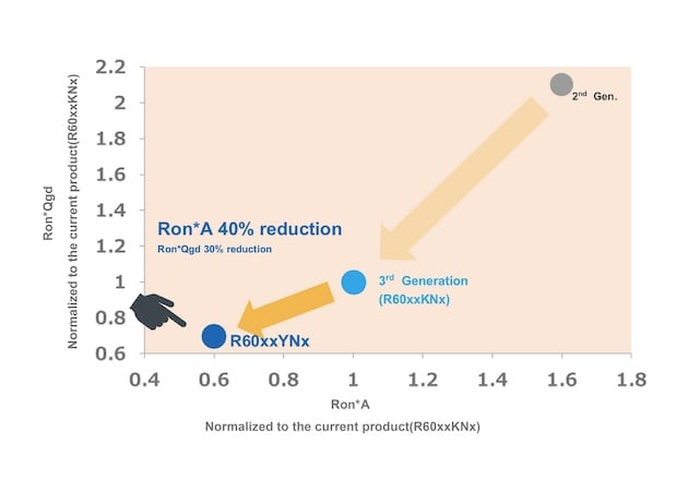
Figure 1. 40% reduction in Ron*A compared to 3rd generation SJ MOSFETs
ROHM’s SJ MOSFETs can achieve up to a 30% lower figure of merit (FOM) for Ron*Qgd. Here, it’s important to note the gate-drain charge (Qgd) which impacts the switching performance of a MOSFET. A low value indicates faster transitions and reduced switching losses, which allows the R60xxYNx series to achieve high efficiency even at high switching frequencies.
Another key benefit of ROHM’s 4th-generation SJ MOSFETs is compact PFC designs at lower costs. Due to the reduced ON-resistance and improved switching performance, these products allow designers to use small heatsinks and passive components, leading to overall system size reduction. Additionally, the competitive pricing of ROHM’s SJ MOSFETs makes them attractive for cost-sensitive applications without compromising on performance.
R60xxYNx Series Super Junction MOSFETs
ROHM offers a comprehensive lineup of SJ MOSFETs suitable for PFC applications. The series includes a broad range of ON-resistance values, ranging from 21 to 324 mΩ, catering to various power levels and efficiency requirements.
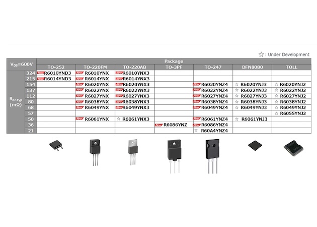
Figure 2. ROHM’s lineup of SJ MOSFETs
Key Benefits & Performance Advantages
One of the main features of the R60xxYNx series is the high threshold voltage (Vth) rating. The higher Vth ensures lower switching-off losses, making these devices ideal for various BCM and DCM PFC designs. In these operating modes, the MOSFET turns off when the inductor current reaches zero, minimizing turn-off losses and contributing to overall efficiency. The R60xxYNx is available in popular package options, including through-hole and surface-mount. Through-hole options include TO-247, TO-3PF, TO-220AB and TO-220FM, which are suited for high-power applications and offer excellent thermal performance. Surface-mount types—TO-252—are more compact solutions for space-constrained applications. Additionally, ROHM is developing two new package options, the DFN8080 and TOLL, to further expand the flexibility available to engineers and designers.
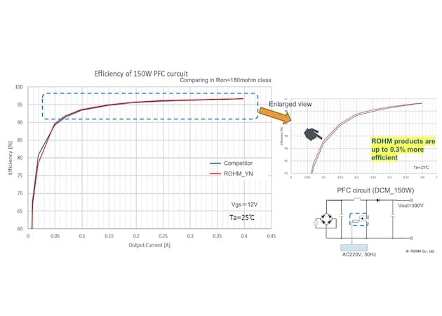
Figure 3. Efficiency improvement vs. competing 180 mΩ MOSFET
ROHM conducted rigorous application testing and benchmarking to validate the performance advantages of the R60xxYNx series in PFC applications. One notable evaluation is a 150W single-phase DCM PFC design, where the R60xxYNx MOSFET demonstrated a 0.3% efficiency improvement compared to a 180 mΩ MOSFET. Such efficiency gain is remarkable, considering the already high efficiency levels achieved in PFC circuits. The performance of the R60xxYNx series can be attributed to their lower on-resistance, fast switching speeds, and high Vth. These characteristics work synergistically to reduce conduction losses, minimize switching losses, and optimize the overall efficiency of the PFC circuit.
Conclusion
SJ MOSFETs achieve a combination of low on-resistance, fast switching speeds, and low gate charge and gate-drain charge, making them beneficial for PFC circuits. With a 40% reduction in specific on-resistance and a 30% lower Ron*Qgd figure of merit compared to 3rd generation, these MOSFETs set a new benchmark for efficiency and switching performance.
ROHM's commitment to quality and reliability, combined with extensive application engineering support, makes the R60xxYNx series a compelling choice for designers seeking to enhance the efficiency and performance of their PFC designs.
For more information about ROHM's SJ MOSFETs or to discuss your specific application requirements, please visit the website or contact ROHM online.
This Industry White Paper was written by Heath Hiroyuki Ogurisu, ROHM Semiconductor.
