
 Facebook
 Google
 GitHub
 Linkedin
Industry White Paper
Functional Safety Shouldn’t Start at Certification
Late-stage safety reviews often expose MCU and firmware gaps that force board re-spins. Building safety into the architecture early changes how a design reaches certification.
Imagine bringing in an independent functional safety assessor just weeks before your industrial controller or robotic drive reaches design freeze. Instead of a routine review, the assessor uncovers fundamental architectural gaps:
- The microcontroller lacks hardware memory error checking.
- The watchdog timer shares a clock tree with the main processor core.
- Safety-critical shutdown routines sit in the same unprotected memory space as untrusted network and user-interface code.
At that stage, no amount of test paperwork can rescue the schedule. The only path forward is a costly PCB re-spin and a ground-up firmware redesign.
That late-stage crisis happens when functional safety is treated as a compliance hurdle at the end of development. In reality, it is a day-one architectural choice. It dictates how your hardware detects faults, how your software isolates critical tasks, and how your system reaches a predictable state when components fail. Third-party certification verifies that your engineering choices satisfy the standard. An assessor cannot retrofit safety into a finished product.
Why Late-Stage Safety Reviews Trigger Board Re-Spins
In industrial automation, robotics, and motor control, the foundational functional safety standard is IEC 61508. It governs electrical, electronic, and programmable electronic safety-related systems. It is also the parent of sector-specific standards such as IEC 62061, the machinery-sector implementation of IEC 61508. Machine builders also commonly apply ISO 13849-1, a separate ISO standard that evolved from EN 954-1. IEC 61508 defines four Safety Integrity Levels (SIL 1 through SIL 4). Each level sets limits on dangerous random hardware failures and requires a rigorous process for software design.
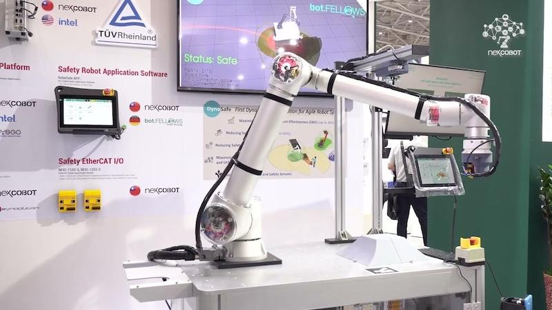
Figure 1. An industrial robot is one example of a system that requires functional safety. Image used courtesy of NEXCOM
When IEC 61508 compliance is deferred until a prototype is running on the bench, four architectural gaps commonly surface in the first assessor review. The first is the absence of a concept-phase hazard and risk analysis. Without it, there is no basis for the target SIL and Hardware Fault Tolerance (HFT).
Another frequent finding is inadequate on-chip fault detection in the microcontroller. For SIL 2 and SIL 3 designs, IEC 61508 sets requirements for Safe Failure Fraction and diagnostic coverage. The processor core, nonvolatile memory, and SRAM all need verifiable diagnostics. A general-purpose microcontroller may lack Error Correction Code (ECC) or parity checking on its internal SRAM. It may also lack an independent clock frequency monitor to catch oscillator drift. In either case, the hardware cannot detect silent bit flips or timing faults before they corrupt an actuator command.
A third gap appears in watchdog and execution-flow supervision. Many embedded designs clock a standard windowed watchdog timer from the same phase-locked loop (PLL) that drives the CPU. If that crystal or PLL locks up, the watchdog freezes alongside the processor.
Finally, assessors often object to firmware architectures that mix safety-critical code with non-safety application code. Suppose the communication stack, human-machine interface, and safety supervision routines share unprotected RAM. Without hardware-enforced freedom from interference, a pointer bug or buffer overflow in a non-safety task can overwrite safety variables.
A Safety-First Sequence for Industrial Designs
During the concept phase, a structured hazard and risk analysis quantifies the severity, exposure frequency, and possibility of avoidance for potential malfunctions. That analysis establishes the SIL target and hardware fault tolerance for each safety function.
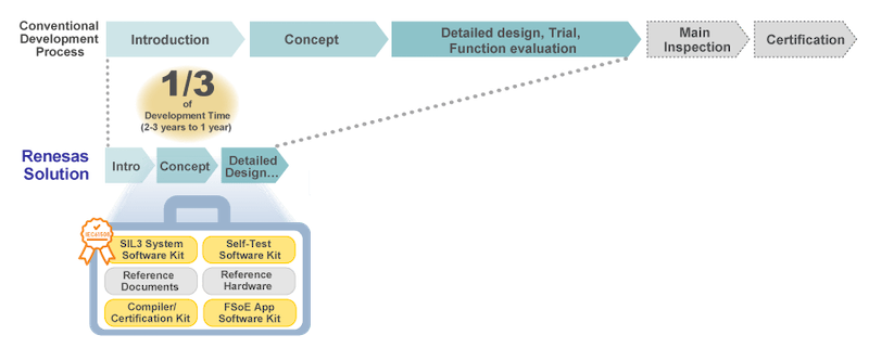
Figure 2. Making functional safety an integral part of the design from the beginning can dramatically reduce development time. Image used courtesy of Renesas
With that target established, you can define the system's deterministic safe state and its fault tolerance time interval. In a servo drive or collaborative robot arm, reaching a safe state typically means cutting gate-drive power to enforce Safe Torque Off (STO). It can also mean de-energizing a 24 V DC safety output module. Either action must happen within a strict millisecond budget when an overcurrent, overspeed, or communication fault occurs.
Those requirements directly inform your choice of system topology and microcontroller family. The goal is silicon with the on-chip diagnostics and partitioning features needed to meet your diagnostic coverage targets. In parallel, cyclic self-tests and structured verification records let audit evidence accumulate alongside your design commits.
NexCOBOT, a Taiwan-based spin-off of NEXCOM, shows the payoff of this safety-first workflow. The company designed its compact NEIO-1103-S and NEIO-1203-S safety digital input/output modules for Functional Safety over EtherCAT (FSoE) systems. The modules needed to meet IEC 61508 SIL 3 with a redundant HFT=1 architecture, as well as ISO 13849-1 PL e, Category 3.
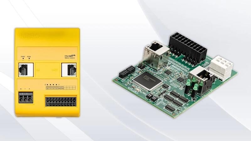
Figure 3. NexCOBOT collaborated with Renesas to develop functionally safe products. Image used courtesy of Renesas
NexCOBOT adopted Renesas’ pre-certified functional safety software kits and self-test libraries, along with reference documentation and technical support. According to Renesas, this approach reduced NexCOBOT’s functional safety development effort by as much as two-thirds, from six years to two. NexCOBOT General Manager Jenny Shern adds that the Renesas support also minimized overall system cost. Similar TÜV Rheinland-certified software kits are now available for RA8 devices.
How the Renesas RA8 Ecosystem Supports Early Safety Architecture
The Renesas RA8 series of 32-bit microcontrollers is built on the Arm Cortex-M85 processor with Helium vector extensions. It pairs high-speed real-time control with IEC 61508 functional safety support.
The family includes the 480 MHz RA8M1 and motor-focused RA8T1, up to the 1 GHz RA8M2 and RA8T2. The 1 GHz devices offer single-core and dual-core options, with a 250 MHz Cortex-M33 alongside the Cortex-M85.
Certified Software Kits
The TÜV Rheinland-certified Renesas Self-Test Software Kit for RA8 detects permanent faults in the CPU, ROM, and SRAM at startup and cyclically during operation. It is certified to Systematic Capability 3 (SC 3) for use up to SIL 3, with diagnostic coverage of 90% for the CPU and data area tests and 99% for the code area test. Separate certificates cover Cortex-M85-only [PDF] and dual-core Cortex-M85/Cortex-M33 [PDF] RA8 devices.
For redundant and partitioned architectures, the TÜV Rheinland-certified SIL3 System Software Kit [PDF] manages cross-monitoring between dual microcontrollers, cyclic scheduling, and software separation. On RA8, it supports the RA8D1, RA8M1, and RA8T1. Its partitioning helps integrators achieve freedom from interference up to SIL 3, so safety routines and non-safety code can coexist on one device. Renesas says this partitioning also simplifies re-certification.
Certified diagnostic coverage for the system kit ranges from 90% for on-chip peripheral control registers to 99% for RAM error detection and program-sequence monitoring. Both kits are available free of license fees through an online request on the Renesas IEC 61508 Functional Safety for Industrial Applications page.
On-Chip Hardware Safety Features
Beneath the software, RA8 silicon adds hardware features for fault detection and isolation. The RA8M1 and RA8T1 datasheets list SRAM with ECC or parity protection. An Arm Memory Protection Unit (MPU) and Arm TrustZone partition memory and peripheral access. On dual-core devices such as the RA8M2 and RA8T2, one core can handle safety and motor control while the other handles communications and application tasks.
A Clock Frequency Accuracy Measurement Circuit (CAC) compares a target clock with a reference clock and raises an interrupt when the count falls out of range. An Independent Watchdog Timer (IWDT) resets the MCU or raises an interrupt if software hangs. Cyclic Redundancy Check (CRC) and Data Operation Circuit (DOC) blocks support data verification. The Port Output Enable for GPT (POEG) module can place GPT output pins in an output-disable state, which helps drive motor PWM outputs to a safe condition.
Three Questions to Answer Before Your First Schematic
First, ask what the physical safe state of your equipment is and how quickly the hardware must reach it after a fault. Cutting inverter gate drive through a hardware path such as POEG calls for different power-stage protection than a controlled braking sequence before power is removed. This choice shapes your protection circuitry from the start.
Second, ask what Safety Integrity Level and Hardware Fault Tolerance your hazard analysis requires. A single-chip design and a dual-channel (HFT=1) design often lead to different layouts. One uses a single partitioned RA8 microcontroller. The other uses a redundant pair linked for mutual cross-monitoring.
Finally, ask which hardware faults your silicon must catch on its own and which require cyclic software diagnostics. Memory ECC, clock monitoring, peripheral register checks, and program-sequence supervision can then be mapped onto an MCU family such as the RA8 and its TÜV-certified software kits before PCB layout. Doing this early improves your chances of passing certification on the first review.

