
 Facebook
 Google
 GitHub
 Linkedin
Industry White Paper
Improving Measurement Visibility in High Frequency Applications
High-frequency current measurements are only as accurate as the sensing element allows. Discover how ultra-low ESL shunt designs minimize measurement intrusion and improve visibility into circuit behavior.
Modern Power Systems Are Creating a Measurement Problem
Modern high-performance power systems are making high-frequency current increasingly difficult to measure. At sufficiently high current slew rates, the requirement is no longer simply an accurate resistance value. Engineers need visibility into these events to evaluate regulator response, switching behavior, current sharing, stability, and overall power delivery performance.
At the same time, increasing measurement bandwidth changes what constitutes a useful current measurement point. A sensing element that behaves predominantly resistively at lower frequencies can exhibit an increasingly significant inductive response as frequency and current slew rate increase. The measurement structure can therefore become part of the electrical behavior the engineer is attempting to observe.
Engineers need a current-sensing structure with insertion inductance low enough that the measurement point does not materially obscure—or disturb—the event being characterized. The challenge is to obtain meaningful current information while minimizing the electrical influence of the sensing structure itself.
Why High-Frequency Current Is Becoming Harder to See
Modern power architectures combine faster switching speeds, high current levels, and increasingly rapid load transients. In integrated voltage regulators (IVRs) and other high-performance power systems, power conversion can occur close to CPUs, GPUs, and ASICs, while multiphase architectures and fast-switching power stages must respond to abrupt changes in load demand. As these systems become faster, engineers need to observe shorter current transients without introducing enough impedance to alter them.
The challenge can emerge before the final processor is even available. During development, a programmable transient load can emulate the rapid changes in current demand expected from a CPU, GPU, or ASIC. Engineers can then observe how the regulator and power delivery network respond to these simulated load transients before the final processor is available.
The measurement chain can be viewed as:
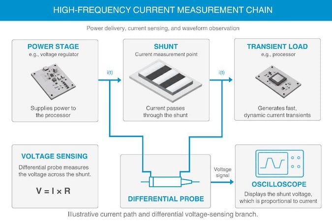
Unlike an external observation point, a shunt sits directly in the current path. Current passes through the sensing element, and the resulting voltage is measured to determine current. As transient speeds increase, that distinction becomes critical. The measurement point must provide visibility into what is happening in the power path while introducing as little electrical disturbance as possible.
Increasing Bandwidth Is Not Enough
Increasing bandwidth can help engineers observe faster events, but it does not remove the parasitic effects of the measurement path. A high-bandwidth oscilloscope and probe can only measure the signal delivered to them. The shunt, PCB layout, probe connection, fixture, common-mode environment, and interconnects can all influence the signal. Determining the limiting factor therefore requires examining the measurement system rather than considering oscilloscope bandwidth in isolation.
The challenge becomes more significant when using a shunt because the sensing element is physically inserted into the power path. Ideally, the voltage across the shunt is proportional to the current flowing through its known resistance. In practice, the structure also introduces parasitic inductance, commonly described as equivalent series inductance (ESL).
Increasing instrument bandwidth does not eliminate that inductance. Instead, the measurement system can begin resolving frequency content where the electrical effects of the sensing structure become more significant. More importantly, because load current passes directly through the shunt, excessive insertion inductance can potentially influence the circuit behavior being measured.
The high-frequency measurement problem is therefore not simply about seeing a faster signal. It is about maintaining measurement fidelity while minimizing the measurement point's influence on the system.
The Physics Behind the Measurement Gap
A perfect shunt converts current into a measurable voltage according to:
V = IR
Because resistance is known, the measured voltage can be used to calculate the current passing through the device. In practice, however, a physical shunt is not purely resistive. Its structure also introduces parasitic inductance.
The resulting voltage can be represented more completely as:
V = IR + L(di/dt)
Because V = L × di/dt, even a small amount of inductance can produce meaningful voltage when current changes rapidly.
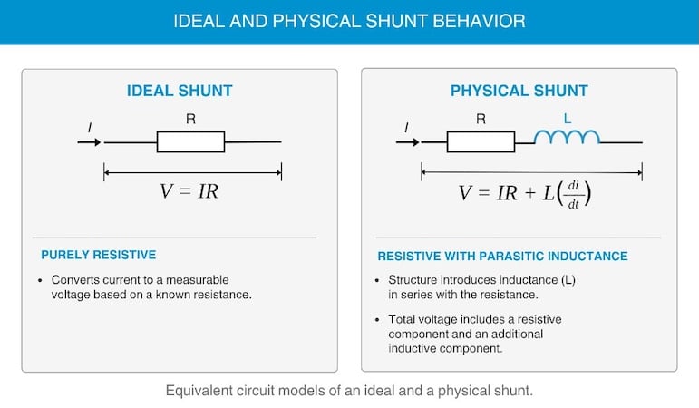
This produces two related engineering challenges:
- Measurement fidelity: As L(di/dt) becomes significant relative to IR, the measured voltage no longer represents current through the known resistance alone.
- Measurement intrusion: Because the shunt is part of the current path, its insertion inductance can influence the circuit being measured.
Where Existing Measurement Approaches Reach Their Limits
Current measurement is not a one-method problem. Engineers have a toolbox that includes conventional shunt sensing, inductor DCR sensing, MOSFET RDS(on) sensing, integrated or on-die sensing and telemetry, external current probes or transformers, and dedicated measurement points. Each approach addresses different system requirements and carries different trade-offs.
The question is not which sensing technology is universally preferable. It is which measurement approach provides the required current visibility while introducing sufficiently little electrical disturbance for the conditions being evaluated.
ATP's Solution: An Ultra-Low-ESL Shunt
Through its Advanced Technology Platform division, TFT is developing an ultra-low-ESL shunt designed to reduce the insertion inductance of the resistive current measurement point. Reducing L reduces the L(di/dt) voltage generated by the sensing structure for the same current transient. The goal is to keep the measured voltage dominated by the resistive IR response while minimizing the shunt's interaction with the power path.
Unlike approaches that compensate for inductance elsewhere in the measurement chain, TFT’s ultra-low ESL shunt addresses unwanted inductance directly at the sensing element. This distinction becomes important when measuring rapid current changes, where even small amounts of parasitic inductance can introduce additional voltage and influence the observed waveform. By reducing insertion inductance, the sensing structure is designed to preserve the relationship between current and measured voltage while limiting its electrical interaction with the circuit.
Recent engineering measurements provide a more detailed understanding of the ultralow-ESL shunt's electrical behavior across frequency. As part of ongoing technology development, different shunt configurations are being evaluated to understand their electrical characteristics and potential applications.
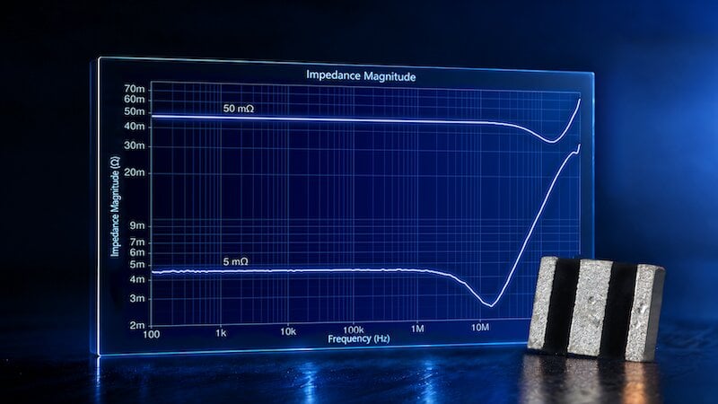
Recent testing included two samples with different physical constructions and nominal resistance values of 5 mΩ and 50 mΩ, characterized using an Omicron Bode 500 impedance analyzer with a Picotest CTF PM-1 interface. The samples were mounted on gold evaluation boards, with impedance and equivalent series inductance evaluated through frequency sweeps extending from 100 Hz to 450 Hz.
Measurements of the 5 mΩ shunt indicate approximately 20 pH of ESL, with relatively stable impedance and inductive behavior across the measured frequencies. These results characterize the shunt's low-inductance performance but do not establish a specified operating bandwidth.
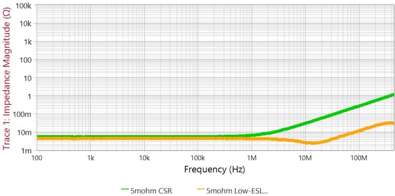
The 50 mΩ shunt provides higher bandwidth while demonstrating similarly low insertion inductance at higher frequencies. Measurements again show ESL values of approximately 20 pH, while impedance remains within the specified tolerance. These results establish a measured high-frequency reference for the shunt and demonstrate why both impedance and ESL must be considered when evaluating a resistive current measurement point.
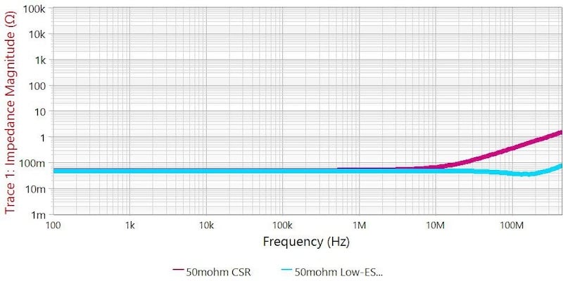
These measurements highlight the advantages of TFT's ultra-low-ESL shunt within the broader range of current-sensing solutions. While existing technologies offer low-inductance performance, they often introduce tradeoffs in physical size, connection requirements, and integration complexity. TFT's ultra-low ESL shunt combines measured picohenry-level insertion inductance with a compact surface-mount design. This combination provides engineers with a practical approach to high-frequency current measurement without the additional integration challenges associated with more specialized sensing solutions.
TFT's measured results demonstrate substantially lower insertion inductance than values reported for many conventional current-sensing shunts. While resistance values, device geometries, and measurement conditions vary, these results highlight the potential advantages of the ultra-low-ESL design for high-frequency current measurement. However, these figures represent different resistance values, device geometries, and measurement conditions. They provide useful engineering context rather than a controlled, head-to-head performance comparison. The results demonstrate that insertion inductance must be evaluated alongside impedance stability rather than treated as a single value independent of frequency. Although the analyzer captures behavior across the broader sweep, the measurements allow engineers to observe how impedance and ESL change with frequency and identify ranges where the electrical behavior is relatively stable.
The significance of lower ESL follows directly from the relationship V = L(di/dt). For the same current transient, reducing insertion inductance reduces the additional noise generated by the sensing element. This can improve the ability to distinguish the desired resistive measurement from the inductive contribution, particularly when current changes rapidly.
This addresses both sides of the high-frequency measurement problem. Lower insertion inductance reduces the inductive contribution to the measured voltage while also reducing the impedance introduced into the power path. The result is a direct resistive measurement point designed to provide current visibility in high-frequency environments without allowing the sensing structure itself to dominate the measurement.
The value of the shunt is therefore not simply "more bandwidth." It is a measurement point designed to minimize parasitic inductance, with its performance being evaluated across different frequencies and measurement conditions. The measured results establish the electrical characteristics of the shunt, while application-level testing will determine where those characteristics provide the greatest improvement in measurement fidelity.
Where This Need Appears in Real Engineering Work
This requirement can emerge at several locations within advanced power systems. Potential measurement points include total IVR or VRM output current, individual phase currents, power-stage current, current entering a processor package, specific power rails, MOSFET or GaN switching currents, and current sharing between phases.
IVR and power-stage development illustrates the problem. Engineers may need to characterize current behavior approaching 100 MHz while maintaining visibility into fast transient content. Reducing measurement bandwidth may produce a cleaner or more usable waveform, but it can also remove information about the high-frequency behavior being investigated. In these environments, the limiting factor must be identified across the complete measurement chain. The shunt, probe, fixture, layout, common-mode behavior, and instrument can all contribute.
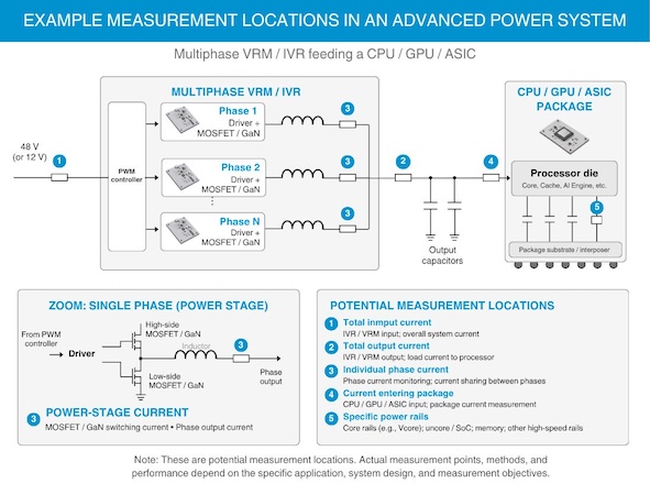
In any given application, engineers must determine which elements of the measurement chain are limiting current visibility and whether insertion inductance at the measurement point is contributing to the problem.
What Engineers Should Evaluate
The important question is not whether a system has reached a particular frequency. It is whether the inductive contribution of the measurement structure has become significant relative to the resistive signal. That depends on shunt resistance, insertion inductance, current magnitude, di/dt, measurement location, PCB layout, probe connection, fixture characteristics, and required bandwidth. Comparing IR with L(di/dt) provides a useful starting point for determining when ESL can no longer be ignored.
Filling a Specific High-Frequency Measurement Gap
High-frequency current measurement requires more than the right instruments. The measurement point itself can influence both the accuracy of the results and the behavior of the circuit being evaluated.
Through ATP, TFT is advancing an ultra-low-ESL shunt that offers a different approach by reducing insertion inductance directly at the sensing element. Early engineering measurements demonstrate promising low-inductance performance, opening opportunities to investigate where this technology can improve current measurement in advanced power systems.
Do you have a current project or design challenge you would like to discuss? Reach out to us here to begin the conversation.

