
 Facebook
 Google
 GitHub
 Linkedin
Industry White Paper
LED Lighting in Software-Defined Vehicles
The transition to software-defined vehicles is fundamentally reshaping automotive E/E architectures, and lighting systems are no exception.
Cars have come a long way since their inception at the beginning of the 20th century. With the continued implementation of additional functions, both safety- and comfort-related, vehicles rely on software more than ever. The increased functionality has inevitably brought complexity to the vehicle’s structure and wiring.
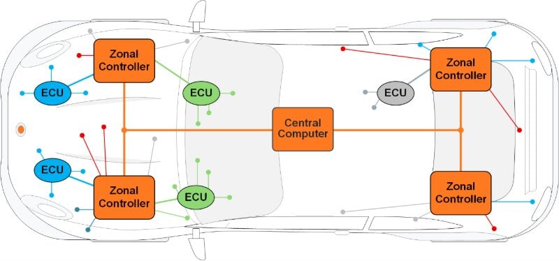
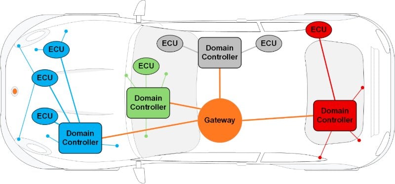
Figure 1. Domain Architecture (top) and Zonal E/E Service Oriented Architecture (bottom).
Traditionally, vehicle electronics were organized into functional domain blocks (powertrain, chassis, HVAC, lighting, etc.), each with its own control units and wiring network. Domain architecture evolved from legacy centralized architecture, in which power was delivered directly to individual electronic control units (ECUs). On the other hand, in domain architecture, the power is delivered to domain controllers and from them to the respective ECUs. The problem is that each added function requires its own ECU, wiring harness, and software. The wiring harness connecting everything becomes longer and heavier, and software integration becomes difficult. The ECUs and domains use a plethora of communication standards such as LIN, CAN, and FlexRay, while in-vehicle central communication is based on Ethernet. Therefore, gateways are required between various communication standards, increasing costs and complexity. This architecture is not sustainable as complexity and intelligence continue to increase.
Image used courtesy of Freepik
Software-Defined Vehicles
Software-defined vehicles (SDVs) are cars engineered to be highly dependent on software, with a centralized computing architecture that can dynamically control, modify, and add vehicle functions via software updates. This is a departure from traditional vehicles, where functionality was largely fixed by hardware at production and managed by numerous distributed ECUs. SDVs consolidate control in powerful central computers, enabling frequent over-the-air (OTA) software updates and new feature deployments long after the car leaves the factory.
In an SDV, this model is fundamentally changed. Instead of dozens of independent computers, an SDV features a unified electronic/electrical (E/E) architecture centered on a powerful central computer (or a few central processors). Software that used to reside on many separate ECUs is now consolidated into these central computing units. This centralized approach means much of a car’s behavior can be altered or enhanced by updating software rather than changing hardware. Ensuring robust cybersecurity and safety is a key requirement in this paradigm, as more critical functions are reliant on software and connectivity.
Software-defined vehicles bring several advantages to modern vehicles. They decouple hardware from software, which enables rapid production cycles. SDVs support updates that can add features, enhance performance, or fix issues and bugs. This helps SDVs retain their value. The updates can be delivered over-the-air (OTA), meaning customers don’t need to go to the shop to receive them.
Automotive Ethernet
Ethernet is an obvious choice for unifying communication within the vehicle. Ethernet usage brings many advantages, including higher bandwidth than legacy communication protocols. While ECUs associated with simple functions might continue with legacy protocols, it is expected that complex functions like ADAS, which require more processing power, will adopt Ethernet. This transformation brings improved efficiency, lower costs, less weight, and enhanced Ethernet security features.
Using point-to-point Ethernet architecture (Figure 2), although it improves speed and removes gateways, is not an ideal solution because it requires a large number of PHYs, increasing system costs. This architecture requires complex switch management of connections, and each ECU is connected directly to the CPU, which increases wiring harness complexity.
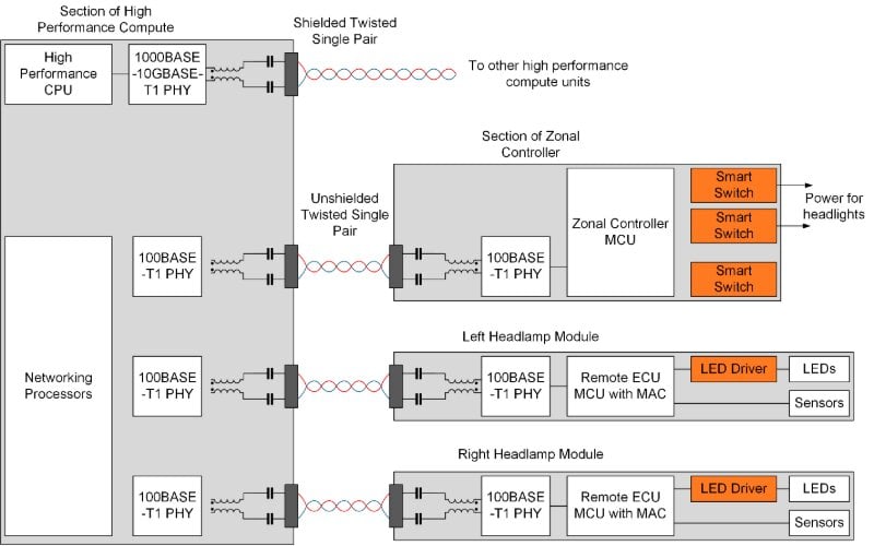
Figure 2. Automotive Ethernet Point-to-Point Connections.
In late 2019, the IEEE ratified the 802.3cg specification, which addresses this fragmentation by introducing 10BASE-T1S: a 10 Mb/s, multi-drop, collision-free, Ethernet standard running on unshielded, twisted, single-pair Ethernet (SPE).
10BASE−T1S, or short reach, is a Physical Layer specification for 10 Mb/s Ethernet LAN over a single balanced pair of conductors (typically 26 AWG cable) up to at least:
a. A minimum of 15 meters reach, full duplex, across a point-to-point (P2P) topology, or
b. A minimum of 25 meters reach, half-duplex, across a multi-drop topology, supporting a
minimum of 8 nodes or stations. The nodes may be attached in-line with the mixing segment, or
at the end of stubs with a maximum length of up to 10 cm stubs.
The use of a multi-drop Ethernet topology (Figure 3) simplifies wiring and saves space, translating to less weight and system costs. In a 10BASE-T1S LAN, any node can send and receive frames to and from any other node.
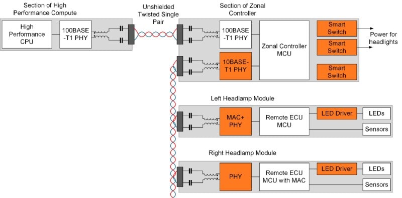
Figure 3. Automotive Ethernet Multi-Drop Connections.
To improve communication quality and avoid packet loss, Physical Layer Collision Avoidance (PLCA) was introduced. Each node is assigned a unique Node ID. ID #0 is called the PLCA coordinator. The other nodes are “followers”. Only the coordinator must know the total number of nodes, including itself. ID #0 issues a BEACON (20-bit symbol), triggering a PLCA cycle (above); then all the nodes reset their “Transmit Opportunity Timers”. Based on its Node ID, each node takes its turn to issue a COMMIT symbol onto the bus, beginning with Node 0. A COMMIT symbol informs all the nodes that an Ethernet Frame is forthcoming. If a node has nothing to transmit during its turn, that node is simply SILENT. Recognizing the absence of a COMMIT symbol (SILENCE), all the “Transmit Opportunity Timers” quickly time out, triggering the next Node ID’s turn to COMMIT to transmit. The use of PLCA-enabled Physical Layers
in CSMA/CD half-duplex shared-medium networks can provide enhanced bandwidth and improved access latency under heavily loaded traffic conditions.

Figure 4. PLCA Physical Layer Collision Avoidance.
onsemi has released the T30HM1TS2500, an automotive-qualified Ethernet transceiver with an integrated Media Access Controller (MAC-PHY). T30HM1TS2500 can communicate with multiple nodes connected to a shared medium at 10 Mbps. The device includes the PLCA Reconciliation Sublayer (RS) and conforms to Open Alliance TC6 specs for Configuration and Data Frames to Host MCUs. T30HM1TS2500 is shipped in a compact 32-pin QFN package.
Evolution of Lighting Architecture
Transformation to the SDV has a visible impact on automotive lighting. Historically, vehicle lighting was relatively static: headlights and tail lamps were controlled by simple switches and basic electronics to turn on/off or toggle between low and high beam. Recently, LEDs became prevalent as a light source, enabling new features like adaptive headlights.
However, the functionality of LED headlights remained limited by distributed electronics. The lamp contains a dedicated lighting ECU, which runs proprietary software implementing LED control to create beam patterns or daytime running light signatures. The car’s central body controller sends simple commands (e.g., turn on/off, dim) via CAN bus.
With centralized computing and high-speed networking, the vehicle’s main software platform can directly orchestrate lighting functions at a much more granular level.
Software-Free (or MCU-less) headlamps are essentially smart LED drivers and fixtures with no onboard controlling MCU, rather than containing its own microcontroller and firmware. All high-level lighting control software runs in the central or a zonal controller, which sends real-time commands to the light units. The headlamps only execute instructions from the central software. This centralization allows the (OEM) to directly code and update how the headlights perform, without needing to rely on the headlamp supplier to pre-program every feature. For example, brightness levels of individual LEDs or pixels in the headlamp can be adjusted on the fly.
With this software-driven control, the adaptive lighting can evolve faster than before. Modern Adaptive Driving Beam (ADB) systems continuously shape and steer the light beam based on sensor inputs. An SDV can use data from cameras, radars, and navigation maps to decide in real time which LEDs to dim or brighten, creating glare-free high beams that mask out oncoming vehicles and illuminate only the needed areas. This precise control requires a high data rate and complex computing, an ideal use case for a single, high-performance central controller.
RCP-Based Electronics Architecture
Remote Control Protocol (RCP) is a lightweight communication technology, aimed to ease the transition towards zonal architecture and the simplification of the overall IVN towards an All-Ethernet approach. With the use of RCP, complexity can be shifted toward a reduced number of centralized computing platforms, hence reducing the size, complexity, and cost of peripheral devices.
RCP is essentially a communication interface that lets a central computer directly control peripheral devices (like LED drivers, sensors, motors) over a single-pair Ethernet network. An RCP controller acts as a bridge, converting Ethernet data to local control signals (SPI, PWM, I²C, etc.) without needing a host MCU at the device. This allows a headlamp to be part of the Ethernet network as a node, receiving high-level commands from the central unit. Importantly, RCP is being standardized via the OPEN Alliance to ensure an open, interoperable protocol for all automakers and suppliers.
RCP removes the need for a dedicated MCU and software in the lamp, reducing hardware complexity and shortening development cycles and time to market. The RCP-based architecture and its comparison to the domain and zonal architectures are visualized in the figure. Compared to the legacy architecture, all of the high-performance computing and the hardware abstraction layer (HAL) are located outside of the lamp. Whereas in the past the LED driver module (LDM) would receive simple commands to control functions (e.g., low beam on), in the MCU-less paradigm, the LDM receives direct commands to switch specific LEDs or LED strings.
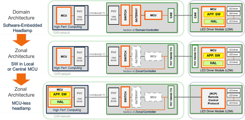
Figure 5. Lighting Architecture.
onsemi GEN4+ LED driver family was developed to be compatible with the newest trends in automotive lighting, including zonal architecture and SDVs. They are state-of-the-art devices that meet major market requirements for automotive LED lighting. They boast advanced device diagnostics, including ASIL B in compliance with ISO26262 on the device level, and full LED string diagnostics and 48V system compatibility. Furthermore, the devices possess secure SPI communication at up to 4 MHz and stand-alone mode with an auto-recovery option. Gen4+ family features fully integrated temperature compensation that outperforms solutions using an external shunt resistor. This innovative solution limits current error to less than 1% over the full temperature range. The GEN4+ family consists of buck (NCV78935 and NCV78925), boost (NCV78902), and boost-buck combined (NCV78964) devices, which complement each other to help create a tailored LDM solution.
Conclusion
By combining centralized computing, Automotive Ethernet, and emerging technologies such as 10BASET1S and RCP, vehicle lighting can evolve from functionally isolated subsystems into fully software-controlled elements of the SDV platform. MCU-less headlamps and centralized control enable faster development, innovation, and reduced hardware complexity. onsemi tackles these changes with new products, including 10BASET1S Ethernet transceivers and a GEN4+ LED driver family. With these solutions, OEMs and Tier1suppliers are equipped to implement scalable, safe, and future-ready lighting architectures that align with the broader SDV vision.

