Facebook
 Google
 GitHub
 Linkedin
A 60 W Class-AB Audio Amplifier: A TDA7296-Based Single-Channel Power Amp
Learn how to construct a robust DMOS-based board featuring mute and standby controls. It easily drives 4 or 8 Ω loads for your next custom stereo or speaker project.
The 60 W Class-AB Audio Amplifier is a single-channel power amplifier board built around the STMicroelectronics TDA7296. This Class-AB amplifier is suited to a wide range of applications, including home stereo systems, self-powered speakers, and high-end televisions.
The TDA7296's high supply-voltage rejection enables a wide voltage range. Its high output current capability lets it deliver maximum power into both 4 and 8 Ω loads
A built-in muting function with a turn-on delay allows smooth remote operation and helps eliminate unwanted switching noise during power on/off. The mute and standby pins each require an external 5 V supply to operate. Screw terminals are provided for the speaker, power input, and audio input signal, and a 3-pin header brings out the standby and mute control voltages. Figure 1 shows the assembled board.
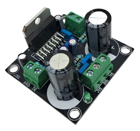
Figure 1. The assembled 60 W Class-AB Audio Amplifier board, built around the TDA7296.
Specs and Features
- Operating voltage range: ±35 V
- Load impedance: 4 ohms or 8 ohms
- Key IC: TDA7296, DMOS power stage, Class-AB
- Output power: up to 60 W music power
- Muting and standby functions, each requiring an external 5 V control signal
- No switch on/off noise
- No Boucherot cell required for most loads
- Very low distortion and noise
- Short-circuit protection and thermal shutdown
- PCB mounting holes: 4 x 4 mm
- PCB dimensions: 51.44 mm x 50.17 mm
Note: the Boucherot cell (R8, C10) is normally not necessary for stable operation, but it may be needed in the presence of particular load impedances at VS < ±25 V (R8 = 2.7 ohm, 1/2 W and C10 = 100 nF/100 V).
How It Works
The TDA7296 is a single-channel Class-AB audio power amplifier with a DMOS output stage. Audio enters through the inverting input (pin 2) via the 470 nF coupling capacitor C5, with R3 and R4 setting the closed-loop gain. The non-inverting input (pin 3) is referenced through the mute switch block, which is controlled by the MUTE and STBY pins (9 and 10). Both are driven from the CN3 header through R5 and R6, with C3 and C4 setting the turn-on/turn-off timing to suppress audible pops.
Bootstrap capacitor C9, connected between the BOOTSTRAP pin (6) and the output, lifts the drive voltage for the high-side DMOS device above the positive rail, letting the output swing to within a diode drop of +VS. The device runs from split ±35 V rails (+VS and −VS), bulk-filtered by C1 and C3 with C2 and C4 providing high-frequency bypassing.
Internal thermal shutdown and short-circuit protection circuitry guard the DMOS output stage without external components. Figure 2 shows the manufacturer's typical application and test circuit, which this board follows closely.
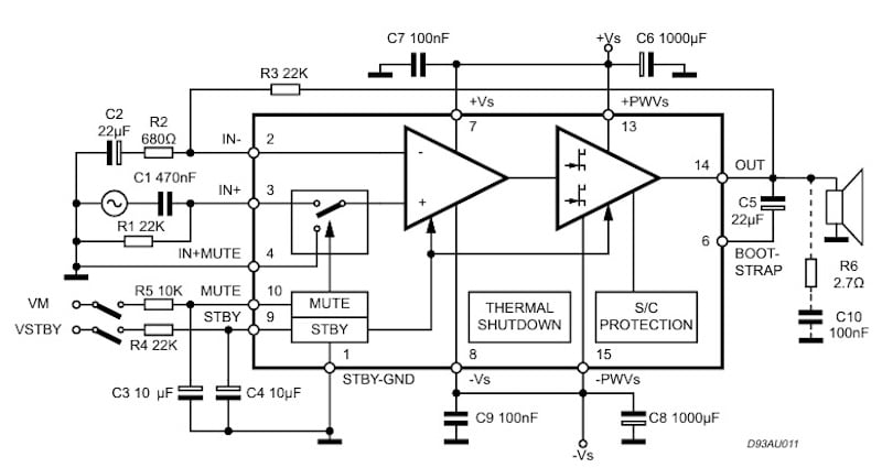
Figure 2. Typical application and test circuit for the TDA7296, showing the mute/standby switching and protection blocks. Image used courtesy of STMicroelectronics.
Schematic and Bill of Materials
The full schematic for the 60 W Class-AB Audio Amplifier is shown in Figure 3.
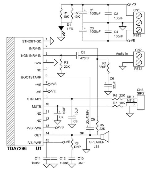
Figure 3. Schematic of the 60 W Class-AB Audio Amplifier board.
The bill of materials is shown in Table 1.
Table 1. BOM for the 60 W Class-AB Audio Amplifier.
| REF | DESCRIPTION | QTY | MFG | SUPPLIER | PART NO. |
| CN1 | 3 Pin Screw Terminal, Pitch 5.08 mm | 1 | Phoenix | Digikey | 277-1248-ND |
| CN2 | 2 Pin Screw Terminal, Pitch 5.08 mm | 1 | Phoenix | Digikey | 277-1247-ND |
| CN3 | 3 Pin Male Header, Pitch 2.54 mm | 1 | Wurth | Digikey | 732-5316-ND |
| C1, C3 | 1000 uF / 50 V Electrolytic, 18 mm dia. | 2 | Nichicon | Digikey | 493-1623-ND |
| C2, C4, C11, C12 | 100 nF / 63 V Film Capacitor | 4 | Epcos | Digikey | 495-B32529C0104K006-ND |
| C5 | 470 nF / 63 V Film Capacitor | 1 | Epcos | Digikey | 495-2503-1-ND |
| C6 | 22 uF / 50 V Electrolytic, 6 mm | 1 | Nichicon | Digikey |
|
| C7, C8 | 10 uF / 63 V Electrolytic, 6 mm | 2 | Nichicon | Digikey |
|
| C9 | 22 uF / 50 V Electrolytic, 6 mm | 1 | Nichicon | Digikey |
|
| R8, C10 | DNP | 2 |
|
|
|
| D1 | LED, Green, 3 mm | 1 | Wurth | Digikey | 732-5008-ND |
| LS1 | 2 Pin Screw Terminal, Pitch 5.08 mm | 1 | Phoenix | Digikey | 277-1247-ND |
| R1, R2, R7 | 10 K, 1/4 W, 5%, THT | 3 | Yageo/Stakpole | Digikey |
|
| R3, R5, R6 | 22 K, 1/4 W, 5%, THT | 3 | Yageo/Stakpole | Digikey |
|
| R4 | 680 Ohm, 1/4 W, 5%, THT | 1 | Yageo/Stakpole | Digikey |
|
| U1 | TDA7296, TO-220 | 1 | ST | Digikey | 497-3966-5-ND |
Connections
Figure 4 shows how power, audio, and the speaker connect to the board.
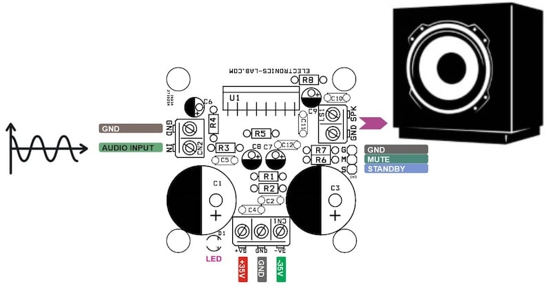
Figure 4. Connection diagram for the 60 W Class-AB Audio Amplifier board.
CN1 — Power Input (3-pin, 5.08 mm pitch):
- Pin 1 = +VS, 35 V
- Pin 2 = GND
- Pin 3 = −VS, 35 V
CN2 — Audio Input (2-pin, 5.08 mm pitch):
- Pin 1 = Audio Input
- Pin 2 = GND
CN3 — Standby / Mute Control (3-pin header, 2.54 mm pitch):
- Pin 1 = Standby
- Pin 2 = Mute
- Pin 3 = GND
LS1 — Speaker Output (2-pin, 5.08 mm pitch):
- Pin 1 = Speaker
- Pin 2 = Speaker
D1 — Power LED:
- Illuminates when supply voltage is present
PCB Files
The PCB measures 51.44 mm x 50.17 mm. The silk screen, top layer, and bottom layer are shown in Figure 5.
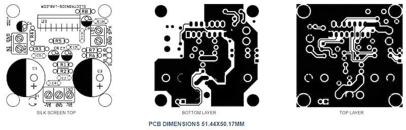
Figure 5. PCB layout for the 60 W Class-AB Audio Amplifier, showing silk screen, top layer, and bottom layer.
You can download the layout files for this project here:
60 W Class-AB Audio Amplifier Gerber Files
Except where noted, all images used courtesy of Rajkumar Sharma