 Facebook
 Google
 GitHub
 Linkedin
Create Your Own Battery Backup Power Supplies
In this project, Jason Poel Smith builds a battery backup system that you can use for small electronics to make sure that they never lose power.
Learn to build a battery backup supply for small electronics so you never run out of power.

There are a lot of electronics that need to be reliably on all the time. Alarm clocks are a good example of this. If the power goes out in the middle of the night and your alarm doesn’t go off, you could miss a very important appointment. The simplest solution to this problem is a battery backup system. That way, if the grid power drops below a certain threshold, the batteries will automatically take over and keep everything running until the grid power is restored.

Materials:
DC Power Supply
Rechargeable Batteries
Battery Pack
Voltage Regulator (optional)
1k ohm Resistor
2 x Diode (rated for a higher current than the power supply)
Male DC Connector
Female DC Connector

The Circuit
There are many different kinds of battery backup systems, and the type that you use is largely dependent on what you are powering. For this project, I designed a simple circuit that you can use to power low power electronics that run at 12 volts or less.
First, you need a DC power supply. These are very common and come in a variety of voltages and current ratings. The power supply connects to the circuit with a DC power connector. This is then connected to a blocking diode. The blocking diode prevents electricity from the battery backup system from feeding back into the power supply. Next, a rechargeable battery is connected using a resistor and another diode. The resistor allows the battery to be slowly charged from the power supply, and the diode provides a low resistance path between the battery and the circuit so that it can power the circuit if the voltage of the power supply ever drops too low. If the circuit that you are driving requires a regulated power supply then you can simply add a voltage regulator onto the end.
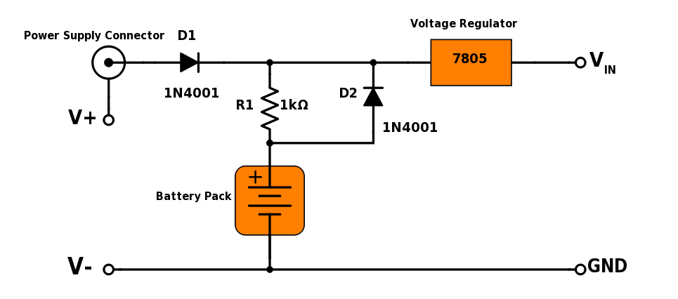
If you are powering an Arduino or similar microcontroller, you should keep in mind that the Vin pin and the DC power connector are already connected to an internal voltage regulator. So you can connect any voltage between 7V and 12V directly to the Vin pin.

Choose the Resistor Value
The value of the resistor needs to be chosen carefully so that the battery isn’t overcharged. To figure out which value resistor you should use, you first need to consider your power supply. When you are working with a non-regulated power supply, the output voltage is not fixed. When the circuit that it's powering is turned off or disconnected, the voltage at the output terminals goes up. This open circuit voltage can be as much as 50% higher than the voltage label on the housing of the power supply. To check this, take a multimeter and measure the voltage at the output terminals of the power supply while no other circuit is connected. This will be the maximum voltage of the power supply.
A NiMH battery can be safely charged at a rate of C/10 or one-tenth of its capacity per hour. Once the battery is fully charged, however, continuing to apply this amount of current could quickly damage it. If a battery is to be continuously charged over an indefinite time period (such as in a battery backup system), then the charge rate needs to be very low. Ideally, you will want the charge current to be C/300 or less.
In my case, I'm using a battery pack that is made from AA NiMH batteries that have a capacity of 2500mAh. To be safe, I want the charge current to be 8mA or less. Given this, you can calculate what the value of the resistor needs to be.
To calculate the necessary value of your resistor, start with the open circuit voltage of the power supply, then subtract the voltage of the fully charged battery pack. This gives you the voltage across the resistor. To find the resistance, divide the voltage difference by maximum current. In my case, the power supply had an open circuit voltage of 9V and the voltage of the battery pack was about 6V. This gave a voltage difference of 3V. Dividing these 3 volts by the current of 0.008 amps gives a resistance of 375 ohms. So your resistor should be at least 375 ohms. I used a 1 kohm resistor to be extra safe. Keep in mind, however, that using a larger resistor will slow down the charging significantly. This isn’t a problem if the backup power system is very rarely used.
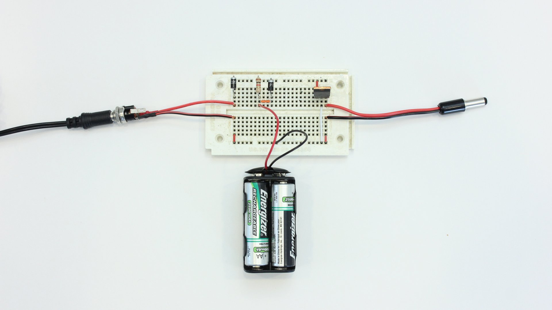
Using Your Battery Backup Power Supply
Using the battery backup circuit that I designed, you can plug your power supply into a female DC power connector. This is connected to the battery backup circuit. Then at the output of the battery backup circuit, there is a male DC power connector that can plug into the electronic device that you want to power. This simple plug-in design means that you don’t have to modify either the power supply or the appliance.
Give this project a try for yourself! Get the BOM.


I have several problems with this circuit. First, the calculations for the current limiting resistor are based on fully charged alkaline batteries (1.5 V/cell). However, NiMH have a nominal 1.2-1.25 V/cell fully charged, and 0.9-1.0V when discharged resulting in a higher trickle charging current. Fortunately, you started with an extremely conservative charge rate of C/300 and more than doubled your resistor. Energizer’s application guide suggests a trickle charge of C/40. Second, NiMH cells do not work well when only performing a trickle charge. The charging current must have an initial rate large enough to break-down crystalline accumulation on the electrodes inside the cell. Crystal formation inside the cell will reduce the capacity and may result in your backup not performing when needed. Third, there is no over-charge protection. Fortunately, the tiny charging current should be able to be dissipated as heat without any hazardous temperature increase, but the internal structure and chemistry of the cell will slowly decay and permanently destroy the battery. Finally, the open battery voltage of 4 1.25V NiMH cells is 5V which is well outside the nominal input voltage for the 7805 to operate. At best, the 7805 will give you a voltage drop, but as the cells quickly drop to 1.2 V and lower, the 7805 may not pass any voltage at all.
In addition to what Adam mentions, the article suggests measuring the output of your unregulated supply with no load to get the peak output voltage. However, depending on the filtering present in your supply the reading you get could be significantly below peak. MEasuring the voltage across a reasonably sized capacitor (say, >1uF) should give you the actual peak voltage as the capacitor will filter out any ripple as it charges.
What about something even simpler: if you leave out the resistor entirely, then the battery is not charged at all, but can still provide an alternative source of power (I think) if primary power fails. If primary power rarely fails and the battery is rarely used, wouldn’t that be sufficient to provide occasional brief backup power? That’s both a question and a suggestion.