 Facebook
 Google
 GitHub
 Linkedin
Learning PLCs on a Budget
Typically, getting started with a PLC can be a costly endeavor, but this project will show how to get started with them on a small budget!
PLCs are used in all sorts of industries: food processing, industrial testing, automation tasks, robotics, etc. Understanding how PLCs work, basic terminology and the ability to write logic for them can be a valuable skill for any engineer! Typically, getting started with a PLC can be a costly endeavor often running into the hundreds of dollars, but this project will show how to get started with them on a small budget.
Gather the Parts!
The very first thing is to grab all the parts needed for programming, setup, and a basic project.

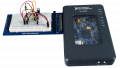
1. PLC and related accessories: This is by far the most critical component needed! Keep in mind that some accessories may also be required, such as a programming cable and programming software. In this project we are going to use a Velocio.net ACE PLC. Starting at $50 with free software and utilizing a standard USB cable for programming, it's a great low cost option.
2. Input Devices: Every project needs a way to acquire data. There are tons of different options like proximity sensors, thermocouples, motion sensors and switches. For this project, to keep costs low, a simple momentary switch will used.
3. Output Devices: In addition to inputs, every project needs outputs of some sort. Typical outputs for PLCs can be LEDs, buzzers, or relays. LEDs are low-cost and easy to implement, making them great for an introductory project on a budget.
Just like the inputs, we're going to keep it simple for this project and use an LED for the outputs. In addition to the LED, an appropriate-sized resistor is needed. If you are unsure about what resistor is needed, take a look at this calculator. I'm using a white LED and a 100ohm resistor.
Assemble The Parts
There isn't a ton of assembly work--it will take only a few minutes!
1. LED Assembly. First, the resistor and leads need to be soldered onto the LED. I used 22awg solid core wire, in descriptive colors (red for positive and black for negative). After the photo below was taken, the legs of the resistor were covered with heatshrink.

2. Switch Assembly. Also, wires need to be soldered onto the switch. More 22awg wire and heatshrink was used.

3. Connector Assembly. The ends of the wires were then stripped and inserted into the handy connectors provided by Velocio with the PLC. The position of the wires were determined by the manual for the PLC. The switch’s wires were installed in the +5VDC and B1 (a digital input) terminals. The LED’s wires were inserted into the +5VDC and C1 (a digital sinking output) terminals. Take a look at the image below for more details on this.

4. Completed! Once the wires were inserted into the connectors, all of the assembly was finished!

Upload the Code to the PLC
1. Download the project. Download the file below containing the simple project.
2. Install the vBuilder software. Download, install, and run the vBuilder Software from the manufactures website. Here is the link.

3. Setup Hardware. Plug the PLC into the computer via the USB port and click “Setup Hardware” on the left side of the screen.

4. Auto Setup. A window will appear and click “Auto Setup”. The software will then recognize the PLC.

5. Upload the Logic & Run! Upload the Logic to the PLC. Click the blue and black “V” icon (or hit F6) to upload the software to the PLC. Then click the green triangle, run button to have the PLC enter the running mode.

You now have software running on the Ace PLC. Press and hold the push button for 1 second to turn the LED on. Take a look at the completed project in the video below:
Moving Forward
This tutorial is more about sourcing low cost parts and testing them, future articles will expand on this project with more detailed explanations on many of the topics that were skimmed in this introduction article. Want to get started on your own projects? Velocio has a 300-page manual that covers tons of topics to help get you started.
Give this project a try for yourself! Get the BOM.


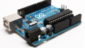


PLC’s tend to be the forgotten workhorses outside the industrial community - MCU’s rules the roost where size matters and complex programs have to be involved. PLC’s are more robust, easier to set up with high level user interfaces than MCU’s, but will do almost as many jobs. By the time you have turned an MCU into a finished project, a PLC will probably not cost a lot more. Where the PLC costs ramp up are adding modules like real time clocks and additional inputs/outputs. A lot of the micro PLC’s and smart relays fit the bill between the large plant automation beasts and the discrete timer/relay jobs