 Facebook
 Google
 GitHub
 Linkedin
Discontinuous Conduction Mode of Simple Converters
Discussed here are the discontinuous conduction mode, mode boundary, and conversion ratio of simple converters.
In this article, we'll go over the discontinuous conduction mode, mode boundary, and conversion ratio of simple converters. During continuous conduction mode, the inductor current in the energy transfer never reaches zero value. In discontinuous conduction mode, the inductor current falls to zero level which is common in DC-to-DC converters.
Origin of the Discontinuous Conduction Mode
During continuous conduction mode, the inductor current in the energy transfer never reaches zero value. In the case of the discontinuous conduction mode, the inductor current falls to zero level which is very common in DC-to-DC converters.
If the peak of the inductor current ripples is less than the DC component of the inductor current, the diode current is always positive and the diode is forced to turn on when the switch S (either a transistor or thyristor) is off. On the other hand, if the peak of the inductor current ripples becomes more than the DC component of the inductor current, the total current falls to zero value while the diode is conducting. Thus, the diode will stop conducting and the inductor current will remain at zero value until the switch S will be gated again due to the polarity reversal across the switch. This gives rise to the discontinuous conduction mode in the chopper or the DC-to-DC converter.
In the discontinuous conduction mode, the inductor current is not persistent throughout the complete cycle and reaches zero level earlier even before the end of the period. Discontinuous conduction mode inductance is less than the minimum value of the inductance for the continuous conduction mode, LDCM < LCCM.
Thus, this condition generally arises for the light-load condition.
Let the value of inductance in the case of the discontinuous conduction mode be: LDCM = ξ LCCM where 0 < ξ < 1 for the discontinuous conduction.
The discontinuous conduction mode usually occurs in converters that consist of single-quadrant switches and may also occur in converters with two-quadrant switches. Two-level DC buck and boost and buck-boost converters will be discussed further in this article. There are two levels indicated here towards the two-voltage level for the inductor voltage.
The energy stored in the inductor is proportional to the square of the current flowing through it. Having the same power through the converter, the requirement of the inductor current is higher in the case of the discontinuous conduction as compared to the continuous conduction mode. This causes more losses in the circuit of the discontinuous conduction. As the energy stored is not yet released to the output in the discontinuous conduction, the output gets affected by the ringing. This may also cause noise in the discontinuous conduction mode.
Moreover, the value of the inductance required for discontinuous conduction mode is lesser as compared to the continuous conduction mode since it allows the fall of the inductor current to zero level. This causes higher values for the root-mean-square and the peak current. Thus, the size of the transformer required in isolated converters is bigger as compared to the continuous-conduction transformer size to suit the larger flux linkage and the losses.
The conversion ratio is independent of the load during the continuous conduction mode but when it enters the discontinuous conduction mode, it becomes dependent on the load. This complicates the DC-circuit analysis because the first-order equations become second-order.
In most of the applications, the continuous conduction mode is employed. Yet, discontinuous conduction mode can also be used for certain applications such as the low-current and loop-compensation applications.
Buck Converter
Consider the simple buck converter circuit shown in Figure 1. The current in the converter is controlled here by two switches labeled S (MOSFET) and D (Diode).
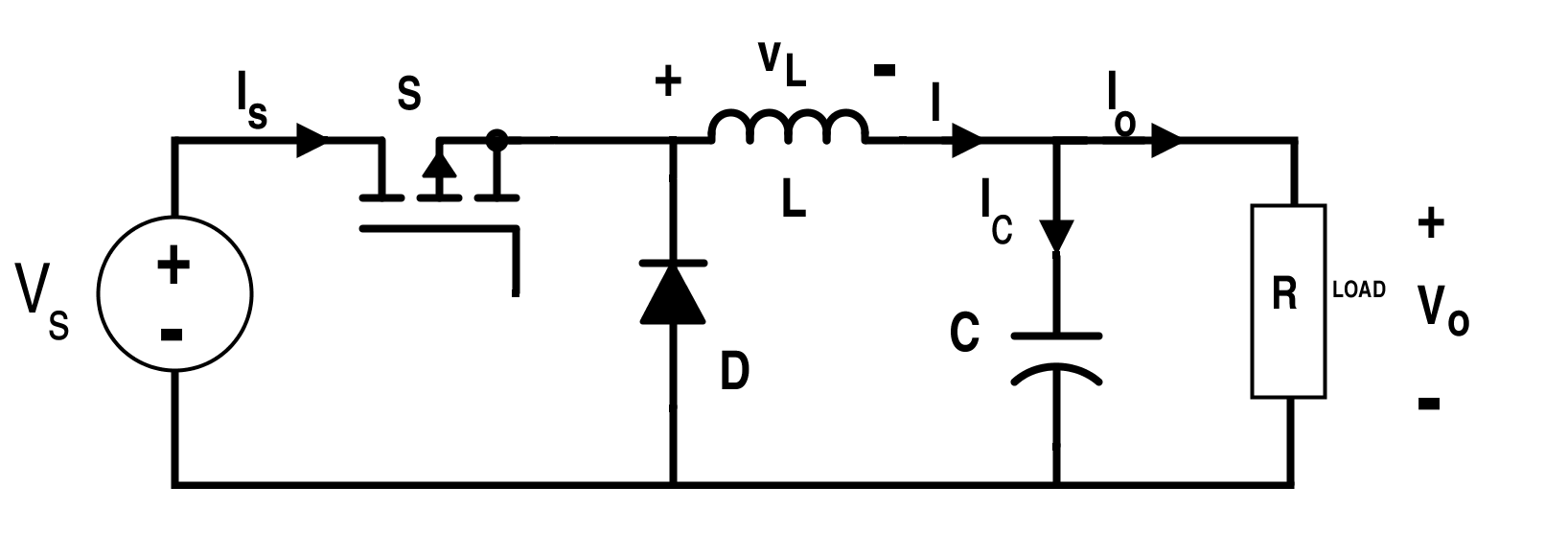
Figure 1. Circuit for buck converter
This is a single-quadrant converter with the following waveforms for the continuous conduction mode shown in Figure 2.
.png)
Figure 2. Supply current IS, diode current ID, inductor current I, and inductor voltage VL waveforms respectively for a buck converter.
The buck converter in discontinuous and continuous conduction modes are in the second-order and first-order systems respectively.
The continuous conduction mode, for 0 ≤ t ≤ DT:
$$I_{L+}=\frac{1}{L}\int_{0}^{t}(V_{S}-V_{O})dt+I_{min}$$
$$\Rightarrow I_{L+} =\frac{V_{S}-V_{O}}{L}t+I_{min}$$
At t = DT, inductor current is at maximum value:
$$I_{max}=\frac{V_{S}-V_{O}}{L}DT+I_{min}$$
Equation 1.
$$I_{L-}=(\frac{1}{L})\int_{DT}^{t}-V_{O} dt+I_{max}$$
For DT ≤ t ≤ T,
$$\Rightarrow I_{L-}=\frac{V_{O}}{L}(DT-t)+ I_{min}$$
Since the inductor is always connected to the load whether the switch is on or off, the average value of the inductor current for the buck converter is:
$$I_{avg}=\frac{V_{O}}{R}$$
The average value of the current through the capacitor is nil due to the capacitor charge balance condition.
From Figure 2, the area under the inductor current waveform is:
$$(Area)_{L} = T I_{min}+\frac{1}{2}T (I_{max}-I_{min})$$
Average value of the inductor current is:
$$ I_{avg}=\frac{V_{O}}{R}=I_{min}+\frac{1}{2}(I_{max}-I_{min})$$
Equation 2.
From Equations 1 and 2 we can get:
$$I_{avg}=\frac{V_{S}-V_{O}}{2L}DT+I_{min}$$
$$\Rightarrow I_{avg}=\frac{D(V_{S}-V_{O})}{2Lf}+ I_{min}=\frac{V_{O}}{R}$$
The value of inductance is:
$$L=\frac{D(V_{S}-V_{O})R}{2f(V_{O}-I_{min} R)}$$
The boundary of the continuous condition is when Imin = 0. If the value of Imin < 0, the converter enters the discontinuous conduction mode.
Which then leads to L = LCCM for Imin = 0 and:
$$L_{CCM}=\frac{D(V_{S}-V_{O})R}{2fV_{O}}$$
The value of inductance for the discontinuous conduction is given by:
$$L=L_{DCM}=ξ L_{CCM}=\frac{ξD(V_{S}-V_{O})R}{2fV_{O}}$$
Where 0 < ξ < 1.
For discontinuous conduction mode, when L < LCCM, the waveforms for the inductor current and inductor voltage are shown in Figure 3.
.png)
Figure 3. Inductor current and voltage for the discontinuous conduction mode of a buck converter.
It is clear from Figure 3 that the value of the minimum inductor current is zero i.e. Imin = 0.
As the current across the inductor current is reduced to zero, the value of the voltage across the inductor is also reduced to zero value while VC = VO during the entire cycle.
For the time duration 0 ≤ t ≤ TON
$$I_{L+}(t)=\frac{V_{S}-V_{O}}{L}t$$
Equation 3.
As the value of the peak inductor current occurs at t = TON,
$$\Rightarrow I_{max}=\frac{V_{S}-V_{O}}{L}T_{ON}=\frac{V_{S}-V_{O}}{L}DT=\frac{V_{S}-V_{O}}{Lf}D$$
For the time duration, TON ≤ t ≤ TX,
$$I_{L-}(t)=\int_{T_{ON}}^{t}-\frac{V_{C}}{L}dt+I_{max}$$
$$\Rightarrow I_{L-}(t)=\frac{V_{C}}{L}(T_{ON}-t)+\frac{V_{S}-V_{O}}{Lf}$$
Equation 4.
At t = TX, current reduces to zero value,
$$0=\frac{V_{C}}{L}(T_{ON}-T_{X})+\frac{V_{S}-V_{O}}{Lf}$$
$$\Rightarrow T_{X}=D\frac{V_{S}}{f V_{O}}$$
Compared to the continuous condition, the amount of energy needed by the load is lesser in the discontinuous condition.
It is considered that the converter is operated in the steady-state. Thus, the energy in the inductor remains the same at the start and at the end of the cycle. The volt-time balance condition can also be applied here.
The above equation can also be derived using the inductor volt-second balance condition as,
$$(V_{S}-V_{C})T_{ON}+(-V_{C})(T_{X}-T_{ON})=0$$
$$\Rightarrow (V_{S}-V_{C})DT+(-V_{C})(T_{X}-DT)=0$$
$$\Rightarrow T_{X}=V_{S}\frac{D}{f V_{O}}$$
For the time duration, TX ≤ t ≤ T
$$I_{L0}(t)=0$$
From Figure 3, it is clear that the average value of the inductor current is equal to the area under the load current curve divided by T.
$$I_{avg}=\frac{\frac{1}{2}T_{X} I_{max}}{T}$$
For the DC supply,
$$I_{avg}=\frac{V_{O}}{R}$$
Hence,
$$\frac{V_{O}}{R}=\frac{V_{S}(V_{S}-V_{O})D^{2}}{2LV_{O} f}$$
The duty cycle ratio for the discontinuous conduction mode in the case of the buck converter is,
$$D=V_{O}\sqrt{\frac{2Lf}{R V_{S}(V_{S}-V_{O})}}$$
Equation 5.
The duty cycle ratio of the buck converter in its continuous conduction mode is:
$$D =\frac{V_{O}}{V_{i}}$$
The duty cycle ratio for the buck converter is also dependent on the inductance L, load resistance R, and the switching frequency f.
For discontinuous conduction mode,
$$L=L_{DCM}=ξL_{CCM} =\frac{ξD(V_{S}-V_{O})R}{2fV_{O}}$$
Equation 6.
Substitution of the Equation 5 into Equation 6 gives,
$$D=\frac{V_{O}}{V_{S}}\sqrt{ξ}$$
Equation 7.
Since 0 < ξ < 1, the duty cycle ratio of the buck converter in the discontinuous conduction mode is less than its value in the continuous conduction mode. Thus, less amount of energy is transferred through the converter which is not enough to maintain the inductor current throughout the entire period. This is the reason the discontinuous current flows through the inductor.
The conversion ratio of buck DC-to-DC converter is,
$$\frac{V_{O}}{V_{S}}=\frac{D}{\sqrt{ξ}}$$
Where 0<ξ<1.
If the value of ξ is greater than 1, the converter enters the continuous conduction mode. We can easily know the conduction state of the buck converter, which is either continuous or discontinuous if we know the value of input and output voltages of the converter by simply measuring the value of ξ.
The instantaneous value of the capacitor current is given by subtracting the value of the inductor current from the load current. When the inductor current value is reduced to zero value, the load current is supplied by the capacitor.
From Equations 3 and 4 we can get, for the time duration 0 < t:
$$I_{C+}(t)=\frac{V_{S}-V_{O}}{L}t-I_{O}$$
Equation 8.
For the time duration DT < t < TX,
$$I_{C-}(t)=\frac{V_{O}}{L}(DT-t)+\frac{D(V_{S}-V_{O})}{Lf}-I_{O}$$
Equation 9.
And for the time duration TX < t < T,
$$I_{C_{O}}=-I_{O}$$
Equation 10.
If the capacitance is assumed to be ideal, the capacitor current will not decay even after the inductor current value is reduced to zero value. For that case, the waveforms for the capacitor and inductor current are shown in Figure 4.
From Figure 4, it is clear that the value of the capacitor current is zero at time t = Ta and at t = Tb.
Equation 8 at time t = Ta gives,
$$0=\frac{V_{S}-V_{O}}{L}T_{a}-I_{O}$$
$$\Rightarrow T_{a}=L\frac{I_{O}}{V_{S}-V_{O}}$$
Equation 11.
And Equation 9 at time t=Tb gives,
$$0=\frac{V_{O}(DT-T_{b})}{L}+\frac{D(V_{S}-V_{O})}{Lf}-I_{O}$$
$$\Rightarrow T_{b}=DT-\frac{LI_{O}}{V_{O}}+\frac{D(V_{S}-V_{O})}{fV_{O}}$$
Equation 12.
The positive time interval for the charge accumulation i.e. Tb-Ta from Equations 11 and 12 is given by:
$$T_{b}-T_{a}=D\frac{V_{S}}{fV_{O}}-\frac{LI_{O}V_{S}}{V_{O}(V_{S}-V_{O})}$$
Equation 13.
From Equation 6 and Equation 7 we can get,
$$T_{b}-T_{a}=\frac{2\sqrt{ξ}-ξ}{2f}$$
Equation 14.
From Figure 4, it is also clear that the maximum value of the capacitor current occurs at the time t = DT.
.png)
Figure 4. Inductor current and capacitor current respectively for the discontinuous conduction mode of the buck converter.
At t = DT,
IC(DT) = Ihp
From Equation 8 we can get,
$$I_{hp} = (\frac{2}{\sqrt{\xi}}-1)I_{O}$$
Equation 15.
The charge accumulated is the integration of the capacitor current (area under the capacitor current from Ta to Tb) which is also given by the expression:
∆Q = C∆V
Equation 16.
Thus,
$$C ∆V=\frac{1}{2}(2\sqrt{ξ}-ξ)(\frac{2}{\sqrt{ξ}}-1)I_{O}(\frac{1}{2f})=\frac{V_{O}(2-\sqrt{ξ})^2}{4Rf}$$
The ripples in the load due to the ripples in the capacitor are given by the following expression:
$$r=\frac{∆V}{V_{O}}=\frac{(2-\sqrt{ξ})^2}{4Rf}$$
Boost Converter
The circuit for the boost converter is shown in Figure 5.
.png)
Figure 5. Circuit for the boost converter.
The waveform for the continuous conduction mode is shown in Figure 6.
.png)
Figure 6. Supply current, diode current, inductor current, and inductor voltage respectively for a boost converter.
When it is in the discontinuous conduction mode, the waveform is shown in Figure 7.
.png)
Figure 7. Inductor current and voltage for the discontinuous conduction mode of a boost converter.
We can assume that the inductor is connected to the load for the time Ty such that,
IO =Y Iavg
Equation 17.
Where:
$$Y = \frac {T_y}{T} $$
When the converter operates in the steady-state condition, the energy at the start and at the end of the cycle is the same. Thus, the volt-time balance condition can be applied here too.
From the figure and the volt-time balance condition, it is clear that TON VS + ( TX – TON) and (VS – VC) = 0.
$$\Rightarrow DT V_{S}+(T_{X}-DT).(V_{S}-V_{O})=0$$
$$\Rightarrow T_{X}=D\frac{V_{O}}{(V_{S}-V_{O})f}$$
From Figure 6, it is also evident that the value of the minimum and maximum currents are Imin = 0 and:
$$I_{max}=\frac{V_{S}}{L}T_{ON}=\frac{V_{S}}{Lf}D$$
Thus, the average value of the inductor current is:
$$I_{avg}=\frac{1}{1-D}\frac{V_{O}}{R}=\frac{\frac{1}{2}T_{X}I_{max}}{T}$$
$$\Rightarrow \frac{V_{O}}{R}=\frac{(\frac{1}{2})(\frac{DV_{O}}{(V_{S}-V_{O})f})(\frac{V_{S}D}{Lf})(1-D)}{T}$$
From Equation 17 we can get:
$$D=\sqrt{2\frac{(V_{O}-V_{S})Lf}{RYV_{S}}}$$
Equation 18.
The duty cycle ratio of the buck converter for the continuous conduction mode is equal to:
$$\frac{V_{O}-V_{S}}{V_{S}}$$
In the discontinuous conduction mode, the duty cycle ratio of the boost converter is not only dependent on the input and output voltages but also depends on the inductance L, load resistance R, and the switching frequency f.
The discontinuous inductance for the boost converter is:
$$L_{DCM}=ξY R\frac{V_{S}(V_{O}-V_{S})}{2 f V_{O}}$$
Substituting this value of inductance in Equation 18 we can get:
$$D=\frac{V_{O}-V_{S}}{V_{O}}\sqrt{ξ}$$
$$\Rightarrow \frac{V_{O}}{V_{S}}=\frac{V_{S}}{1-\frac{D}{\sqrt{ξ}}}$$
Hence, the complete conversion ratio for the boost converter in the discontinuous conduction mode is given by the above expression.
Buck-Boost Converter
The circuit for the buck-boost converter is shown in Figure 8 and the related waveforms of the buck-boost converter in the case of continuous conduction mode are shown in Figure 9.
.png)
Figure 8. Circuit for the buck-boost converter

Figure 9. Supply current, diode current, inductor current, and inductor voltage respectively (buck-boost converter) in continuous conduction mode.
The inductor is connected to the load during the switch-off period; where Y= (1-D).
Thus,
$$I_{avg}=Y I_{O}=Y\frac{V_{O}}{R}=\frac{(1-D)V_{O}}{R}$$
.png)
Figure 10. Inductor current and inductor voltage for the discontinuous conduction mode of the buck-boost converter.
Assume that the converter is operating in a steady state; therefore, energy at the start-up to the end of the cycle must be equal. Thus, the volt-time balance condition is applied here.
Applying the volt-sec balance across the inductor using Figure 9, VS TON + (TX - TON) (-VO) = 0,
$$\Rightarrow V_{S}DT - (T_{X}-DT)V_{O}=0$$
$$\Rightarrow T_{X} = \frac{D(V_{S}+V_{O})}{V_{O}f}$$
From Figure 9, it is also noticed that the value of the minimum and maximum currents are Imin = 0.
$$I_{max}=\frac{V_{S}}{L}T_{ON}=\frac{V_{S}}{Lf}D$$
Thus, the average value of the inductor current is:
$$I_{avg} = Y\frac{V_{O}}{R} = \frac{\frac{1}{2}I_{max}T_{X}}{T}$$
$$\Rightarrow \frac{V_{O}}{R}=\frac{\frac{\frac{1}{2}V_{S}D}{Lf}D(V_{S}+V_{O})}{YV_{O}f}f$$
In the discontinuous conduction mode of the buck-boost converter, the value of the duty cycle ratio is given by:
$$D=V_{O}\sqrt{\frac{2Lf}{R YV_{S}(V_{S}+V_{O})}}$$
The duty cycle ratio of the buck-boost converter for the continuous conduction mode is equal to:
$$\frac{V_{O}}{V_{O}+V_{S}}$$
In the case of the discontinuous conduction mode, the duty cycle ratio of the buck-boost converter is also dependent on the inductance L, load resistance R, and the switching frequency f.
The conversion ratio for the buck-boost converter is:
$$\frac{V_{O}}{V_{S}}=\frac{D}{\sqrt{ξ}-D}$$


This article has realized me to think something new. I am working on boost converter TPS61030 and It produces noise and ringing maybe due to the discontinous conduction mode and I want to solve this issue because I want silent device. Is to possible to operate it in continuous conduction mode by using the formula had been derived in this article?