Facebook
 Google
 GitHub
 Linkedin
Introduction to Vibration Energy Harvesting
Learn more about vibration energy harvesting as a source of power for electronic systems.
Learn more about vibration energy harvesting as a source of power for electronic systems.
Each energy harvesting technology has its pros and cons and energy vibration energy harvesting is no exception.
One of the advantages is that vibrations are almost everywhere: on a car, on a train, on an airplane, on a bike, on a washing machine, on the rotor of a wind generator, on a bridge, on skis, on funiculars, on a volcano, etc.
Of course, these vibrations differ from each other for the frequency distribution and for the magnitude. But suitable energy harvesters can be designed to couple with different sources.
Very good coupling is fundamental because it increases the amount of energy transferred from the environment to the transducer. This means that the mechanical impedance of the system must match with that of the source.
In this article, we'll talk about the basics of vibration energy harvesting and look at different types of energy harvesters.
The Basics of Vibration-to-Electricity Conversion
Let's start with something everybody knows, the dynamo, which is an example of an electromagnetic generator. In a dynamo, a magnet moves inside a coil to produce electricity as stated by the law of Faraday and Lenz:
$$\epsilon =\frac{d\omega }{dt}$$
where $$\epsilon$$ is the electromotive force and $$\frac{d\omega }{dt}$$ represents the change of the magnetic flux with respect the time.
But can we consider a dynamo as an energy harvester?
It depends! It is an energy harvester if we use the dynamo to convert wind energy, but it is a simple converter (or energy stealer) when we couple it with a wheel of a bike.
These lines should help to understand that a vibration energy harvester is based on the relative motion of two parts: the source of the energy and the transducer.
The Basic Model of a Vibration Energy Harvester
The following figure shows a very basic model of a vibration energy harvester.
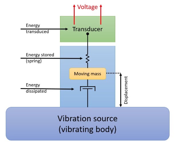
In order to be valid in this model, the mass of the vibration source must be orders of magnitude greater than the mass of the energy harvester; the impact of the last one on the dynamic of the first cannot be neglected.
In this model, the movement of the source is transferred to a moving mass, i.e., the mass of the energy harvester. A part of the energy is dissipated (via friction, etc.) and some heat is produced. A part of the input energy is stored because of the elastic properties of the mechanical parts (here represented by the spring) and released when the direction of motion is inverted. The remaining energy is converted into electricity.
It’s trivial to understand that the efficiency is always less than 1.
From the equation that describes the dynamics of the system, we know that the output voltage from the generator is proportional to the velocity of the displacement. We also know that the output voltage is AC.
Piezoelectric Energy Harvesters
Piezoelectric energy harvesters use a piezoelectric crystal to produce electricity. In a piezoelectric crystal at equilibrium, charges are homogeneously distributed in its volume. When an external force is applied and stress is induced in the structure, this distribution changes and charges start to move in an effort to re-establish the equilibrium.
Different types of stress can be induced:
- Flection
- Torsion
- Compression
- Expansion
- A combination of these
Each time the distribution of charges changes, an electromotive force can be measured and a current can flow to a load.
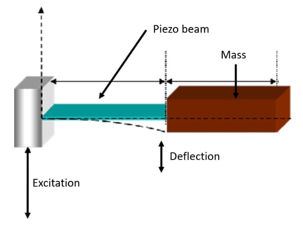
A very common way to induce flection on a piezoelectric is shown in the following image. A vertical excitation induces a flection on the piezo beam because of the inertia of the mass.
Electromagnetic Energy Harvesters
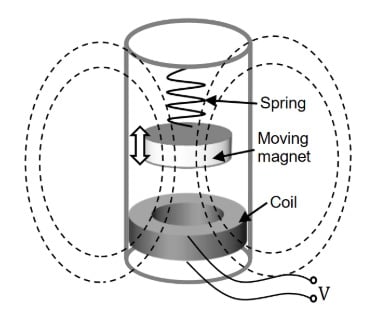
Electromagnetic energy harvesters are similar to piezoelectric harvesters in the sense that a mass is still used to oppose to the excitation—but the piezoelectric material is replaced by a magnet and a coil.
Generally, the magnet is mechanically supportive (free to move) with the moving body (or energy source) while the coil is fixed to the structure of the generator: the important thing is to have relative motion between the two, as is shown in the following picture.
Instead of using moving parts, the coil can be winded directly on a magnetostrictive material. This material is magnetic and has a property wherein its magnetic field changes when it is deformed. This then changes the material's magnetic flux.
Electrostatic Energy Harvesters
Another important way of converting kinetic energy into electricity is represented by electrostatic energy harvesting. This kind of generator generally uses mechanical vibrations to change the distance between the plates of a capacitor or their surface.
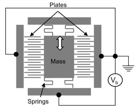
One of the problems with this technology is that the capacitor has to be pre-charged or no electricity can be produced. One way to solve this issue is to use a dielectric material with a particular spatial distribution of charges in order to create a voltage between the plates of the capacitor, even without the use of an external bias voltage: these are the electrets.
Defining the Concept of Linearity
In order to understand the dynamic properties of an energy harvester, it is important to focus the attention on the quantity U(x), i.e., the potential energy related to the displacement x.
The mathematical form of this function is a consequence of the geometry and of the dynamics of the vibration harvester.
Linearity and Resonance
As we've already discussed, one of the most common models of an energy harvester is the so-called cantilever configuration. In the case of small bending, the potential energy grows with the square of the bending and the reaction force of the beam is proportional to the bending.
This can be well described when considering the Galileo’s pendulum: the bending is represented by the displacement of the mass from the vertical position. The action of the gravity is the restoring force that acts on the pendulum mass m.
$$F = -mg \sin \sin \frac{x}{t} $$
where g is the gravity acceleration, x is the displacement and l the length of the pendulum.
For small movements from the vertical position (i.e., small bending) the following approximation is valid.
$$ \sin \sin \frac{x}{t} \cong \frac{x}{t} \rightarrow F = - mg \frac{x}{t} = - kx$$
This means that the force is linearly proportional to the displacement and the potential function of the system can be written as $$U(x) = \frac{1}{2}kx^{2}$$ (harmonic potential).
A system like this is called linear oscillator and it exhibits a resonance frequency. When a periodic external force at the resonance frequency is applied to the system, its response to the excitation is a displacement of maximum amplitude (and thus the energy conversion is maximized).
The Frequency Response of a Vibration Energy Harvester
The frequency response describes how a system reacts to a harmonic signal at different frequencies and it is generally represented with a graph. The frequencies are placed on the horizontal axis while the amplitude of the response in the vertical one. Generally, the amplitude of response can be represented in logarithmic scale.
Such a plot is the basic tool for design, analysis, and understanding of dynamic systems. It can be easily obtained applying a sinusoidal vibration to the harvester (by the means of a shaker) and measuring its output voltage or power. This operation must be repeated for a set of frequencies in order to cover an entire frequency band and maintaining the amplitude of the excitation constant. The number of points on the frequency axis must be enough in order to obtain a detailed plot.
A linear system is very easy to investigate because its response will be strong at the resonance frequency while the response will be much smaller as it gets further away from it. Once the resonance frequency and the relative amplitude have been found, the bandwidth of the system can be evaluated looking for the points where the response decays of 3 dB (70.7% of the amplitude or 50% of the power).
Knowing the resonance frequency and the bandwidth, it is possible to obtain the Q factor (quality factor) of the system: the lower are the losses the narrower is the bandwidth.
For a linear system, the frequency response is well represented by a Gaussian curve as shown below.
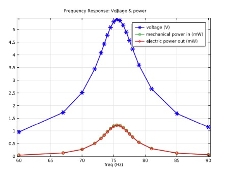
"Power output as a function of vibration frequency." Plot used courtesy of Comsol.
For non-linear systems it is not possible to define a frequency response because the superposition principle is not valid: generally, for these systems, a statistical description is given.
Vibration energy harvesting is an important method of energy harvesting, especially as connected sensor systems grow more popular. If you're looking to power a system that will be difficult to conduct maintenance on but is positioned in a place full of kinetic energy, vibration energy harvesting may be an option!
Would you like to learn more about different types of energy harvesters? Would you find it helpful to learn more about use-cases for different forms of energy harvesting? Share your thoughts in the comments below!
Related Content