 Facebook
 Google
 GitHub
 Linkedin
Keeping the Lights On: A New “Open LED Protector” from Littelfuse
Let’s take a look at how to make your LED array more robust; we’ll use the PLEDxN series from Littelfuse as an example.
Let’s take a look at how to make your LED array more robust; we’ll use the PLEDxN series from Littelfuse as an example.
You’ve probably noticed that LEDs are becoming increasingly common as replacements for traditional light sources. Traffic signals and household light bulbs come to mind. LEDs certainly have their benefits, but one little complication is that you might need multiple LEDs to replace a single incandescent bulb (or fluorescent bulb, or halogen lamp).
This need for multiple LEDs leads to the proverbial Christmas-lights problem: if you have multiple illumination devices in series, a single failure can bring down the entire array. This is annoying, to be sure, but it’s worse than annoying when you really need a functional light source—the datasheet for the PLEDxN series from Littelfuse mentions headlights, roadside warning lights, and airport runway lighting (I sure hope that the airports already have a solid solution for keeping the runway lights on).
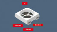
The datasheet mentioned above refers to the “PLEDxN series,” but I see only one part listed, namely, the PLED6N (the “6” refers to the typical breakdown voltage, i.e., VBR = 6 V). So for the remainder of this article I’ll refer to the PLED6N. The device looks like a diode:

All images used courtesy of Littelfuse.
But as you can see from the following diagram, it is actually a diode plus some control circuitry:

As implied by the name “open LED protector,” the PLED6N protects an LED array from a failure in which one of the LEDs becomes an open circuit. The general concept is straightforward: If you have LEDs in series and one fails as an open circuit, current flow through the entire array is interrupted, and you’re in the dark. The PLED6N is connected in parallel with the LED, and if it detects an open circuit, it provides a current path that allows the other LEDs to remain illuminated.
The Details
The datasheet is not overly generous in terms of a functional explanation, but you can infer operational details from the specs and plots.
First let’s look at the current–voltage characteristics:

We see here that the device allows minimal current flow as long as the voltage across its terminals is less than VBR. (We’ll ignore the portion of the graph representing voltages less than zero.) This makes sense; if the LED is conducting, the voltage across the LED (and hence across the PLED6N) will be relatively low, and at low voltages the PLED6N doesn’t have a significant effect on the circuit.
But if the LED has failed and is now acting like an open circuit, we will have a larger voltage across the PLED6N. If this voltage is greater than VBR, the device begins to conduct significant current.
Thus, breakdown voltage is the critical parameter here (hence the inclusion of VBR in the part number). You have to be sure that
- the LED’s forward voltage will never be higher than VBR (otherwise the PLED6N will shunt current away from the LED), and
- the voltage across the PLED6N will exceed VBR in the event of a failure.
I doubt that many applications will need to worry about this, but keep in mind that VBR varies slightly in response to temperature changes:

Thermal Specs
The PLED6N dissipates power like any other part, and we need to make sure that an LED failure is not followed by a different sort of failure involving a burned out PLED6N. The part can handle about 1.5 W at room temperature. The on-state voltage (VT) is about 1 V, though it increases for higher on-state current (IT):

So if you include a little safety margin, you’re looking at a maximum current of about 1 A. If your LED circuit could cause significantly more than 1 A to flow through the PLED6N, you need a different part. Or you could attempt to improve your thermal characteristics such that the actual max power dissipation is higher than the two example values given in the datasheet.
Transient Behavior
The following scope capture conveys some details about how the PLED6N responds to a failure event. Something happens to the LED at the moment corresponding to the scope’s trigger location. The voltage across the PLED6N rapidly increases (and exceeds VBR), then it decreases toward VT as the PLED6N begins to conduct.

Have you used an “open LED protector,” or a different sort of protection scheme for LED lighting? Feel free to share your thoughts in the comments.


In what situation would one wire an array of LEDs in series ? The Christmas tree lights I buy are wired in parallel. Seems like there needs to be a current limiter in series with the PL to protect the circuit from multiple open LEDs.
Are we talking about industrial or commercial lighting here?
In what situation would one wire an array of LEDs in series ? The Christmas tree lights I buy are wired in parallel. Seems like there needs to be a current limiter in series with the PL to protect the circuit from multiple open LEDs.
Are we talking about industrial or commercial lighting here?
i have a doubt that due to the more brightness in led when compared to other lights , it may affect our eyes , right?