 Facebook
 Google
 GitHub
 Linkedin
Requirements for Good Communications Link Performance: IQ Modulation and Demodulation
In this article, we'll discuss the requirements for an analog IQ modulator and demodulator, and then the requirements for DACs and ADCs used at baseband (for an analog IQ approach) and for DACs and ADCs used at RF (for a digital IQ approach).
In the last article, we discussed the quandary of whether it's better to use digital or analog means to combine and separate I and Q.
Here, we'll pick up the topic again by characterizing the requirements necessary for good communication link performance in these analog and digital applications.
Requirements for Analog IQ Modulator and Demodulator
Table 1 shows the results of a literature survey of articles describing the degradation in communications links due to IQ imbalance. OFDM was the modulation for most of the articles.
For the following, please see the previous article for my list of references.
Table 1: Requirements for Analog IQ Modulator and Demodulator
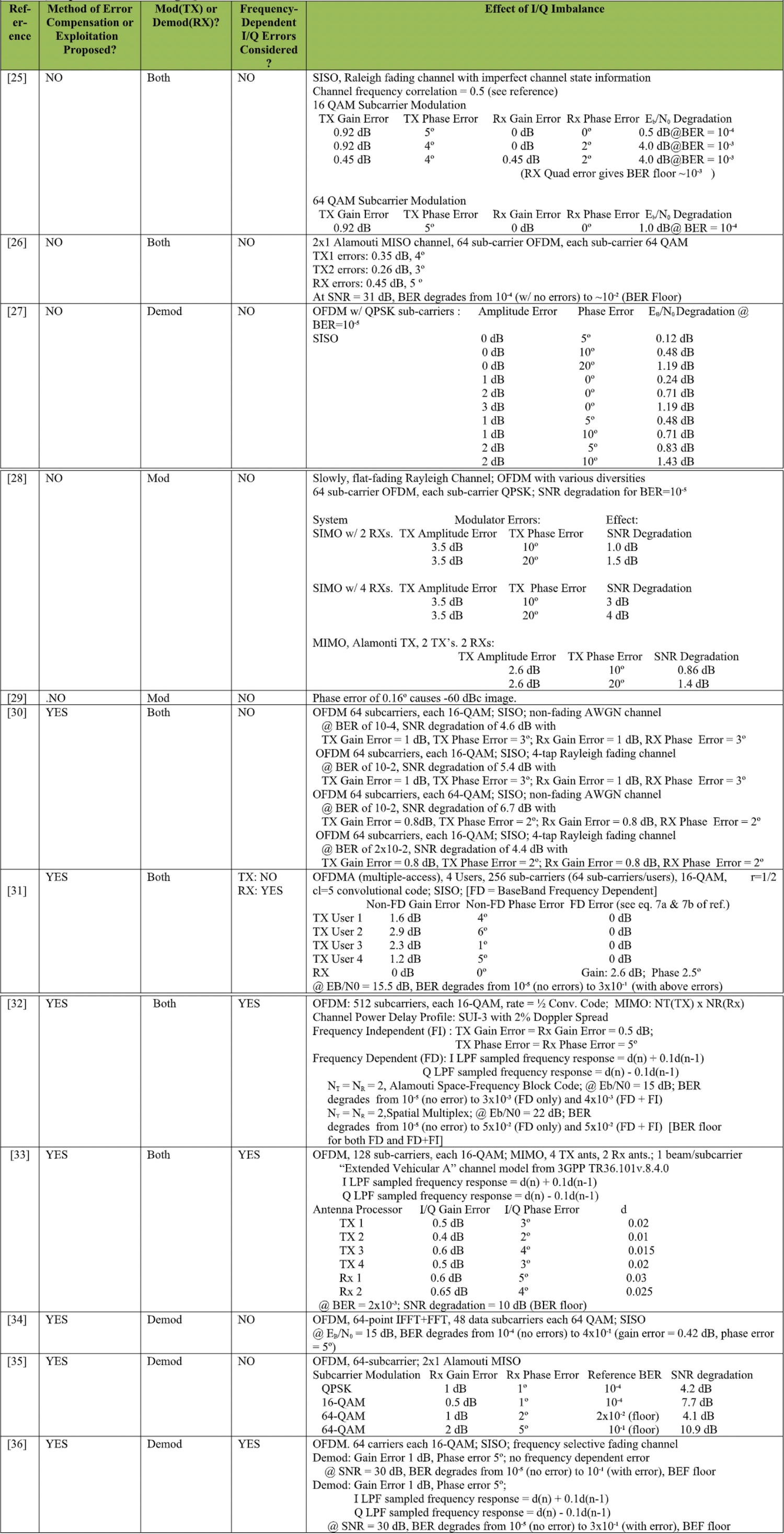
Click to enlarge table to full size
It is possible to draw a few conclusions.
At the modulator (TX) end, IQ imbalances up to 1 dB and 5º give what might be acceptable degradation; 0.5 to 1.0 dB; even with 64-QAM OFDM subcarriers, at bit error rates of 10-4 to 10-5.
The situation is different at the demodulator (RX) end. For N-QAM subcarriers, IQ imbalances of 1 dB and 5º give degradations of many dB, according to most of the articles. For these imbalances, and N > 4, generally there is a bit error rate floor from 10-3 to 10-1. An imbalance of 0.5 dB and 1º gives degradations of ~8 dB for 16-QAM subcarriers at a bit error rate of 10-4.
There are no results given for imbalances less than 0.5 dB and 1º. For N > 16, none of the articles show how small the imbalances must be for degradations to give a bit error rate floor less than 10-3.
This is unfortunate because integrated IQ modulators and demodulators are available with typical imbalances of ~0.02 dB and 0.2º. None of the articles explains why the demodulation is so much more sensitive to IQ imbalances than the modulation.
Requirements for DACs and ADCs
Requirements for DACs and ADCs Used at Baseband for Analog IQ Approach
The analog IQ modulator and demodulator approaches still require data converters in the baseband I and Q paths in position A in Figures 1A and 1B from our previous article.

Figure 1(a). Modulator

Figure 1(b). Demodulator
It is important to know how good these devices must be. The author found there is much less published on this effect than on the IQ imbalance effect. The best that could be deduced is that a Signal-to-Noise+Distortion Ratio (SINAD) of > 38 dB is required.
Requirements for DACs and ADCs Used at RF for Digital IQ Approach
The Digital IQ approaches require data converters in position D in Figures 1A and 1B. The author also found very little published on this subject. There have been some results published of the effects of analog amplifier effects such as 3rd Order Intermodulation Products (IP3) on communications systems, and it might be valid to also apply these to data converters, which has been done.
Generally, it seems a Signal-to-Noise+Distortion Ratio (SINAD) of > 50 dB and a Third Order Intermodulation Product of > 44 dBc are required for acceptable performance degradation.
Table 2. Baseband Data Converter Requirements

Table 3. RF or IF Data Converter Requirements


The text in this article refers to “position A” and “position D” in Figures 1(a) and 1(b). Figures 1(a) and 1(b), as published, do not have “position A” and “position D” labeled. Instead, they both show the ADC or DAC positioned for the Digital IQ Approach.
To properly interpret the Figures for the Digital IQ Approach, there should be a” D” above the DAC in Figure 1(a) and the ADC in Figure 1(b). This puts the Data Converter between the power combiner or splitter, and “RF or IF Analog”.
To reference the Analog IQ Approach, the DAC and ADC as shown in the Figures should be bypassed. There should be an “A” between “”Digital In-Phase Data” and the “Low Pass Filter”, and also an “A” between “”Digital Quadrature Data” and the “Low Pass Filter” in both Figures 1(a) and 1(b).
Later in the article, in the text after “Table 1: Requirements for Analog IQ Modulator and Demodulator”, the exponential notations did not come out correct. The text with direct numerical, rather than exponential notation is given below:
It is possible to draw a few conclusions.
At the modulator (TX) end, IQ imbalances up to 1 dB and 5º give what might be acceptable degradation; 0.5 to 1.0 dB; even with 64-QAM OFDM subcarriers, at bit error rates of 0.0001 to 0.00001.
The situation is different at the demodulator (RX) end. For N-QAM subcarriers, IQ imbalances of 1 dB and 5º give degradation of many dB, according to most of the articles. For these imbalances, and N > 4, generally there is a bit error rate floor from 0.001 to 0.1. An imbalance of 0.5 dB and 1º gives degradation of ~8 dB for 16-QAM subcarriers at a bit error rate of 0.0001.
There are no results given for imbalances less than 0.5 dB and 1º. For N > 16, none of the articles show how small the imbalances must be for degradation to give a bit error rate floor less than 0.001.
This is unfortunate because integrated IQ modulators and demodulators are available with typical imbalances of ~0.02 dB and 0.2º. None of the articles explains why the demodulation is so much more sensitive to IQ imbalances than the modulation.