Facebook
 Google
 GitHub
 Linkedin
DC Electric Circuits
Time Constant Circuits
23 questions By Tony R. Kuphaldt
-
Question 1 of 23
Generally speaking, how many “time constants” worth of time does it take for the voltage and current to ßettle” into their final values in an RC or LR circuit, from the time the switch is closed?
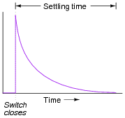
Reveal answerIf you said, “five time constants’ worth” (5 τ), you might not be thinking deeply enough! In actuality, the voltage and current in such a circuit never finally reach stable values, because their approach is asymptotic.
However, after 5 time constants’ worth of time, the variables in an RC or LR circuit will have settled to within 0.6% of their final values, which is good enough for most people to call “final.”
Notes:The stock answer of “5 time constants” as the amount of time elapsed between the transient event and the “final” settling of voltage and current values is widespread, but largely misunderstood. I’ve encountered more than a few graduates of electronics programs who actually believe there is something special about the number 5, as though everything grinds to a halt at exactly 5 time constants worth of time after the switch closes.
In reality, the rule of thumb of “5 time constants” as a settling time in RC and LR circuits is an approximation only. Somewhere I recall reading an old textbook that specified ten time constants as the time required for all the variables to reach their final values. Another old book declared seven time constants. I think we’re getting impatient as the years roll on!
-
Question 2 of 23
Suppose a fellow electronics technician approaches you with a design problem. He needs a simple circuit that outputs brief pulses of voltage every time a switch is actuated, so that a computer receives a single pulse signal every time the switch is actuated, rather than a continuous ön” signal for as long as the switch is actuated:
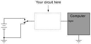
The technician suggests you build a passive differentiator circuit for his application. You have never heard of this circuit before, but you probably know where you can research to find out what it is! He tells you it is perfectly okay if the circuit generates negative voltage pulses when the switch is de-actuated: all he cares about is a single positive voltage pulse to the computer each time the switch actuates. Also, the pulse needs to be very short: no longer than 2 milliseconds in duration.
Given this information, draw a schematic diagram for a practical passive differentiator circuit within the dotted lines, complete with component values.
Reveal answer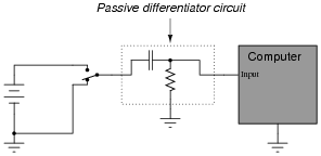
Did you really think I would give you the component values, too? I can’t make it too easy for you!
Challenge question: An alternative design to the differentiator circuit shown above is this:
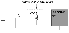
This circuit would certainly work to create brief pulses of voltage to the computer input, but it would also likely destroy the computer’s input circuitry after a few switch actuations! Explain why.
Notes:The behavior of a differentiator circuit may be confusing to students with exposure to calculus, because the output of such a circuit is not strictly related to the rate of change of the input voltage over time. However, if the time constant of the circuit is short in comparison to the period of the input signal, the result is close enough for many applications.
-
Question 3 of 23
When a circuit designer needs a circuit to provide a time delay, he or she almost always chooses an RC circuit instead of an LR circuit. Explain why this is.
Reveal answerCapacitors are generally cheaper and easier to work with than inductors for making time delay circuits.
Notes:The answer given here is purposely minimal. You should ask your students to give responses more thoughtful than this! Ask them why capacitors are cheaper than inductors. Ask them to explain what is meant by ëasier to work with,” in technical terms.