Facebook
 Google
 GitHub
 Linkedin
Designing UWB Antennas for Angle of Arrival Applications
Learn what makes Ultra-Wideband (UWB) unique, what makes it useful, and how to address the design challenges it presents.
Ultra-Wideband (UWB) is a wireless technology defined by the U.S. Federal Communications Commission (FCC) as occupying either:
- A relative bandwidth of ≥ 20% its center frequency.
- An absolute bandwidth ≥ 500 MHz.
The spectrum is usually 3.1–10.6 GHz, unlicensed globally. Unlike narrowband wireless technologies such as Wi-Fi or Bluetooth, which transmit data via continuous sine waves, UWB uses impulse radio. This means that it sends extremely short, low-power pulses—typically nanoseconds to picoseconds in duration—across a wide frequency spectrum.
We'll start off this article by examining what makes UWB useful and what, practically speaking, it's used for. After that, we'll shift our focus to how we can achieve these benefits through proper antenna design. As we'll see, maintaining proper signal isolation can be particularly challenging. At the end of the article, we'll demonstrate an effective solution to this problem by running tests on a UWB device that uses Leankon antennas.
Benefits of UWB
The characteristics of UWB we described above grant it some unique advantages over other wireless technologies. In this section of the article, we'll briefly highlight the benefits of UWB and explain how UWB provides them.
Low Power Consumption
UWB pulses are transmitted infrequently, so average power consumption is extremely low—often less than 1 mW. This makes UWB ideal for wearables, IoT sensors, and other battery-powered devices.
Low EMI
The low power density of UWB pulses (≤ –41.3 dBm/MHz) minimizes disruption to other wireless systems operating in the same spectrum. At the same time, UWB provides strong anti-interference. Its ultra-wide frequency band spreads signal energy across many channels, reducing vulnerability to narrowband interference (from Wi-Fi 6 or 5G, for example).
High Positioning Accuracy
Due to its short pulses, UWB can measure time-of-flight (ToF) with nanosecond-level precision. As a result, it's capable of centimeter-level positioning. This is far superior to Wi-Fi's meter-level or Bluetooth's decimeter-level accuracy.
Angle of arrival (AOA) is another key positioning technique in UWB systems. Whereas ToF measures distance via signal travel time, AOA calculates the direction of a UWB signal source relative to a receiver. When combined with other methods, such as ToF or RSSI, AOA enables full 2D/3D positioning.
AOA relies on a multi-antenna receiver array to achieve precise positioning performance. This is typically two to four antennas spaced at a known distance, called the "antenna baseline." As we'll discuss later on in the article, designing such systems can be challenging. Before we get to that, though, let's look at what UWB is used for in the real world.
Main Applications of UWB Technology
UWB's combination of high accuracy, low power, and anti-interference makes it suitable for scenarios requiring precise localization, secure connectivity, or environmental sensing. In this section, we'll examine its key applications.
Precision Positioning and Tracking
This is UWB's most mature and widely adopted use case, leveraging the centimeter-level accuracy noted in the previous section. It's often used in consumer electronics to provide "Find My Device" features. In iPhones and iPads, for example, Apple's UWB-enabled U1 chip allows users to locate lost AirTags. This location feature is accurate to within 10 cm and includes directional guidance.
UWB is also useful for automating device interactions in smart homes. These include smart lights that turn on when a user approaches and TVs that adjust volume based on the user's position. In automotive applications, UWB enables gesture control for infotainment systems. Perhaps more importantly, it's also used to detect passenger positions. In this way, it enables safety features such as adjusting airbags based on a child's seat location.
Finally, UWB is used for asset and inventory tracking. It can monitor high value-assets, such as medical equipment in hospitals or artworks in museums, with precise location logs. It can also be used to track warehouse inventory, offering real-time localization of pallets, robots, or workers to optimize logistics. For example, Amazon uses UWB for warehouse robot coordination.
Secure Authentication and Access Control
UWB's ability to verify physical proximity, rather than just signal strength, makes it resistant to relay attacks—a common vulnerability in Bluetooth/Wi-Fi. For that reason, automotive manufacturers like BMW and Ford use UWB to enable digital car keys. The car only unlocks if the key (e.g., a smartphone) is within a trusted physical range, preventing relay-based theft.
UWB can also be used to control access to offices, homes, and data centers by authenticating users based on their precise location. For example, it might only grant access if the device is within 50 cm of the reader.
Sensing and Imaging
UWB pulses can penetrate non-metallic materials such as wood and drywall. This enables UWB systems to see conductive materials that are behind barriers. In healthcare, this allows non-contact vital sign monitoring—for example, measuring heart rate or respiration by detecting chest movement via UWB reflections—without requiring wearables.
The applications aren't purely medical. UWB can be used for home security (detecting intruders behind walls), or industrial machinery monitoring (tracking moving parts to prevent collisions). It's also used for short-range, low-power radar, allowing drones to avoid obstacles and robots to navigate tight spaces.
The Challenges of AOA Antenna Design
In UWB systems, high-precision positioning is a core requirement. The antenna plays a pivotal role in enabling this functionality. However, as we mentioned earlier in the article, a UWB system includes two or more antennas.
Integrating two UWB antennas into a single UWB device presents significant challenges for designers. In this section, we'll outline the key hurdles. After that, we'll discuss solutions.
Wide Frequency Bandwidth
UWB systems operate across an extremely broad frequency range, with the primary working band spanning 6–8.5 GHz. This bandwidth is far wider than that of common wireless technologies like Wi-Fi (2.4–2.5 GHz and 5.15–7.125 GHz) or Bluetooth (2.4–2.5 GHz).
To cover this extensive frequency spectrum effectively, a UWB antenna must employ specialized wide-bandwidth design techniques. This is particularly challenging because performance stability must be maintained across the entire band.
High Isolation Requirement
To eliminate mutual interference between the two AOA antennas and ensure optimal positioning accuracy, strict isolation standards must be met. Qorvo's UWB Application Note APH511 makes two recommendations:
- The isolation between the two UWB antennas should be at least –25 dB.
- The physical distance between the antennas should be approximately 0.45 times the wavelength (λ).
A PDF of this application note is available to download via this link.
Omni-Directional Radiation Pattern
An omni-directional radiation pattern is essential for UWB antennas, as it guarantees comprehensive positioning coverage. For most tracking systems, wide coverage is a prerequisite for delivering a smooth user experience. However, designing an antenna that simultaneously achieves wide bandwidth and maintains an omni-directional radiation pattern across the entire operating frequency range remains a significant technical challenge.
Decoupling Techniques to Enhance Isolation
Of the three factors described above, isolation is the most variable. Its stability is highly sensitive to both the wide bandwidth of UWB and the limited space available in compact devices, making it particularly difficult to control.
Several techniques for decoupling the antennas have been developed to address the isolation challenge. For example, one way of reducing signal coupling is to increase the physical distance between the two antennas. Using orthogonal polarizations for the two antennas can also minimize mutual interference.
One might also introduce a dedicated neutralization line to cancel out coupling currents between the antennas. Another solution is to use metamaterials or electromagnetic bandgap structures to block surface waves that contribute to cross-antenna interference.
However, given the constraints of UWB's wide bandwidth and the limited space in miniaturized devices, perhaps the most practical and effective solution is to add a decoupling element. This is a specialized component that generates a decoupling resonance, thereby suppressing unwanted signal coupling.
Application of a Decoupling Element in Practice
Let's look at an example. The test setup we'll use is illustrated in Figure 1.
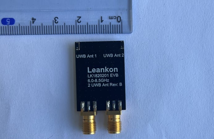
Figure 1. Two Leankon UWB antennas to demonstrate decoupling.
This device uses two Leankon LK1820201 SMD UWB antennas. The PCB dimensions are 30 mm × 21.2 mm × 1 mm.
As noted earlier, Qorvo recommends a distance of 0.45λ between two UWB antennas for AOA applications. For UWB Channel 9 (center frequency = 7.987.2 MHz, BW = 499.2 MHz), 0.45λ translates to approximately 16.87 mm. We're using UWB Channel 9 for this example, so the two antennas in Figure 1 are separated by 16.87 mm.
Figure 2 measures the isolation of the two antennas without any decoupling elements. It also shows the antennas' return loss (S11), a key indicator of antenna impedance matching.
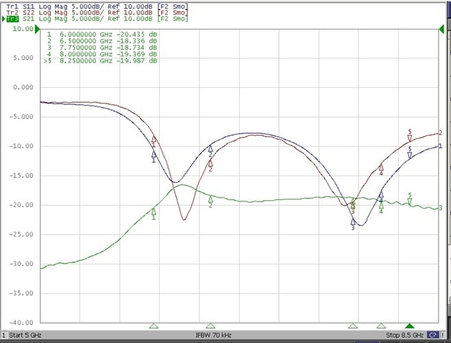
Figure 2. Return loss and isolation of two UWB antennas without decoupling element.
Figure 3 shows the results of integrating a decoupling element between the two UWB antennas.
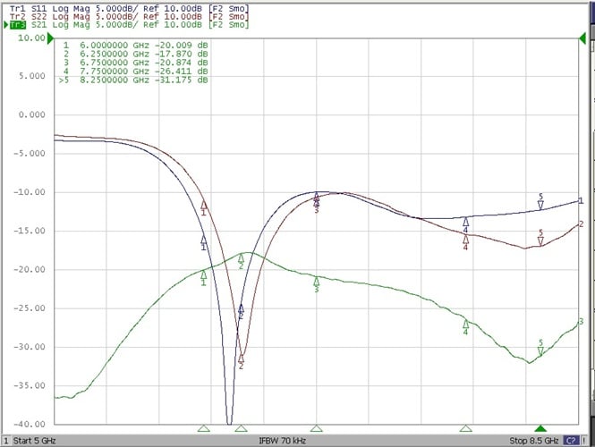
Figure 3. Return loss and isolation of two UWB antennas with a decoupling element.
Comparing Figures 2 and 3, we can see that the isolation has significantly improved. The optimized design achieves an isolation of less than –26 dB across the entire frequency band of UWB Channel 9, surpassing Qorvo's recommended minimum isolation threshold of –25 dB.
This consistent performance across the full operating range ensures that mutual interference between the two AOA antennas is effectively suppressed, laying a solid foundation for high-precision UWB positioning.
Background of featured image used courtesy of Adobe Stock; all other images used courtesy of Leankon
Related Content