Facebook
 Google
 GitHub
 Linkedin
Half-bridge DC-DC Converter Scheme Shrinks Power in Data Centers
To keep power under control, data centers are embracing new rack architectures based on 48 V bus voltages. Learn how to craft a half-bridge DC-DC converter to implement such a 48 V system.
The pressure on to scale up and build new data centers (Figure 1) to meet the increasing demands for data storage. This expansion is ultimately resulting in greater power consumption, along with demands for keeping that power under control.
One highly effective way of reducing the power consumption of a data center is to use the 48 V bus voltage for server racks. That said, such architectures are only practical by using carefully selected, highly efficient MOSFETs.

Figure 1. Data centers invariably require an immense amount of power, but 48 V bus systems are a proven way to reduce power losses—when designed correctly. Image used courtesy of Pixabay
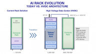
How Open Rack Architecture Addresses Power Loss
To achieve better efficiency, power losses must be dealt with. The Open Rack architecture proposed by the Open Compute Project (OCP) addresses loss of power by using 48 V bus lines rather than conventional 12 V bus lines.
To understand how this works, start by recalling that the power loss caused by a power line is calculated using I2R, where R is the power line resistance, and I is the power line current. Based on this simple relationship between current and resistance, a lower current leads for the same level of resistance will lead to less power loss and more efficiency.
In the case of Open Rack architecture, consider the power consumption when the same amount of power is supplied to server racks through 12 V bus lines vs. 48 V bus lines: the current that passes through a 48 V bus line is only 1/4 the current that passes through a 12 V bus line. Therefore, assuming the 48 V and 12 V bus lines have the same level of resistance, the 48 V bus will consume 1/16 the power of the 12 V one.
Open Rack Using a Half-Bridge DC-DC Converter
To go beyond the theory and to the practical application of Open Rack architecture, consider using a half-bridge DC-DC converter such as that shown in Figure 2. Such a converter can efficiently step down the 48 V bus line voltage to 1.2 V and reduce total system power consumption.

Figure 2. Simplified half-bridge DC-DC converter. Image used courtesy of Toshiba
The largest source of power losses for the half-bridge DC-DC converter lies in switching operations. And, in addition to switching losses, there are also gate drive losses, output capacitance losses, diode reverse recovery losses, and conduction losses—all of which will impact the overall efficiency of the DC-DC converter.

Figure 3. Sources of losses in a step-down DC-DC converter. Image used courtesy of Toshiba
The losses shown in Figure 3 can be significantly reduced through the right choice of power MOSFETs. When choosing the MOSFETs for a half-bridge DC-DC converter (such as the one proposed for use in a 48 V bus system), there are several considerations and major constraints to be considered. Typical characteristics of such as system are shown in Figure 4.

Figure 4. Input and output characteristics for the half-bridge DC-DC converter are shown in Figure 2. Image provided courtesy of Toshiba
As for any MOSFET specification, the input characteristics (input voltage and current) must be established as well as the output characteristics (ripple, switching frequency, voltage, current, and power). In addition, the circuit topology must be known, and whether the MOSFET in question is for the primary or secondary side.
The Toshiba Approach
Using the reference design and parameters shown in Figure 5 and the characteristics summarized in Figure 4, Toshiba has investigated the most effective and practical power MOSFETs needed to achieve the highest efficiency level for a 48 V bus system.

Figure 5. A half-bridge DC-DC converter evaluation board supporting a 48 V bus system. Image provided courtesy of Toshiba.
The block diagram in Figure 6 shows a design developed by Toshiba achieving a total efficiency of 92.8% (Vin = 54.5 V, 30% load) with specific MOSFETs labeled that have proven ideal for achieving high efficiency and minimizing converter size to just 160 mm × 100 mm.

Figure 6. Block diagram of a 1.2 V / 100 A output isolated DC-DC converter for direct conversion of 48 V bus voltage to 1.2 V. Image used courtesy of Toshiba
Because the effect of switching losses dominates the primary side, MOSFET products with small input capacitance are superior, and high efficiencies have been achieved with the TPN1200APL for medium to heavy loads (40 A to 100 A). Such efficiencies are made possible by having both the input capacitance and the on-resistance small, with an on-resistance of only 9.8 mΩ.
On the secondary side, the built-in diodes will operate before the MOSFET is turned on, making conduction losses dominant. Therefore, a MOSFET with a small on-resistance works best, and the Toshiba TPHR6503PL has exhibited high efficiency from medium to heavy loads.
This silicon n-channel MOSFET provides high-speed switching combined with a low drain-source on-resistance of 0.41 mΩ. It also has a small gate charge, output charge, and low leakage current.
All About Reducing Power Consumption
The Open Rack architecture proposed by OCP uses 48 V bus lines to reduce power consumption and efficiency. While half-bridge DC-DC converters supporting the 48 V bus system are one approach to efficient implementation.
They require a careful selection of MOSFETs to be effective. Research performed by Toshiba points to the use of the TPN1200APL MOSFET for the primary side and TPHR6503PL for the secondary side based on a compact, highly efficient design they developed.
Toshiba offers high-quality, efficient MOSFETs with VDSS ranging from 30 V to 250 V, as well as various on-resistance types in each VDSS class, so engineers can find the suitable MOSFET when designing a DC-DC converter.