Facebook
 Google
 GitHub
 Linkedin
Overcoming CAN Design Challenges: Addressing CAN Voltage and Power Challenges
This article discusses some CAN design challenges, focusing on power consumption and designing with multiple voltage rails in a CAN application.
In the first installment of Overcoming CAN Design Challenges, I discussed the intricacies and challenges of designing and terminating the Controller Area Network (CAN) bus. In this second installment, I’ll focus on power consumption and designing with multiple voltage rails in a CAN application.
Calculating power consumption in a CAN transceiver is not as straightforward as it may seem, and adding multiple voltage rails around the transceiver just adds to that complexity. Plus, with all of the different flavors of CAN transceivers, you may find yourself choosing the wrong transceiver, or adding a voltage rail into your system that isn’t necessary.
Question 1: How Do You Calculate the Power Consumption of a CAN Transceiver in Active Operation?
There are multiple aspects to the power consumption of a CAN transceiver. Figure 1 shows the portion of quiescent current needed to power the device while it’s in a recessive state in blue, and the portion needed to drive the dominant levels of the CAN bus in red.

Figure 1. Current flow of a CAN transceiver showing quiescent current needed to power a device.
Correctly assessing a CAN transceiver’s power consumption requires that you know/assume/measure the amount of time that the transceiver is in each bus state, as well as these parameters:
- Current consumption of the transceiver when the bus is in the recessive state.
- Current consumption of the transceiver when the bus is in the dominant state.
- Percentage of overall time that the bus is in the dominant vs. recessive state.
- Differential output voltage in the dominant state.
- VCC supply voltage.
- VIO supply voltage (if the VIO pin is present).
- Input/output (I/O) supply current (if the VIO pin is present).
The current consumption of the transceiver in both states and the amount of time that the bus is in both states is fairly self-explanatory in this calculation. Because the current consumption in either state is significantly different, and the CAN bus state is consistently changing during communication, the amount of time that the bus is in a recessive or dominant state will factor heavily into the transceiver’s power consumption.
The differential output voltage in the dominant state is necessary because some of the power consumed from the VCC supply will be through the termination resistance. Knowing the drop across this resistance will help you determine how much current is being consumed through that resistance.
The differential output voltage in the recessive state isn’t necessary because there should not be a significant voltage drop (or any at all) across the resistor when the bus is recessive; CANH and CANL should be within tens of millivolts of each other, if not the same exact voltage. There is no current through the resistor, and the transceiver is not delivering a significant amount of power to the bus.
Equation 1 expresses the formula for power consumption after knowing all of these variables:
P = [(1-D)*IREC*VCC] + [D*IDOM*(VCC-VOD)]
Equation 2 expresses the formula for transceivers with a VIO pin:
P = [(1-D)*IREC*VCC] + [D*IDOM*(VCC-VOD)] + VIO*IIO
Where P is power, D is percentage of time the bus is in the dominant state, VCC is the supply of the transceiver, IREC is the current consumption from VCC in the recessive state, IDOM is the current consumption from VCC in the dominant state, VOD is the output differential voltage of the bus in the dominant state, VIO is the IO voltage of the device (if there is a VIO pin) and IIO is the device’s I/O current.
Let’s use the TCAN1042 CAN Flexible Data Rate (CAN-FD) transceiver as an example and assume that the device is in the dominant state 50% of the time and in the recessive state 50% of the time. VCC = 5 V, IREC = 1.5 mA, IDOM = 40 mA, VOD = 2.25 V and D = 0.5, plugging these values into Equation 1 results in:
P = [(1-0.5)*1.5*5] + [(0.5)*40*(5-2.25)] = 3.75 mW + 55 mW = 58.75 mW
As you can see, calculating the power isn’t always an intuitive process, but it can be simplified by using the correct parameters.
Question 2: Can a 5V and 3.3V CAN Transceiver Operate on the Same Bus Together?
The short answer is yes, they can. All 3.3V CAN transceivers are designed to have their recessive level and dominant and recessive thresholds such that they will correctly transmit and receive messages from either a 5V or 3.3V CAN transceiver. Within 3.3V CAN transceiver device families, there are two recessive levels: 1.85 V and 2.3 V.
A 3.3V automotive CAN bus transceiver like the SN65HVD230 has a 2.3V recessive level which designed to work optimally with 5V CAN transceivers. Others, like 3.3V CAN transceivers with CAN-FD, like the TCAN330, will also operate well with 5V CAN transceivers, but they are designed with a 1.85V recessive level in order to minimize the individual device’s electromagnetic interference. Industrial applications such as building and security automation and climate control systems will use 3.3V transceivers due to their power savings relative to 5V CAN, and because only 3.3V rails are available in those types of systems.
Question 3: If Your MCU Uses 3.3V as the Logic Supply, Do You Need a 3.3V CAN Transceiver?
Unless you are working with a 3.3V CAN bus, you do not need a 3.3V CAN transceiver. There is a difference between 3.3V CAN transceivers and CAN transceivers that have the ability to accept 3.3V logic levels. 3.3V CAN transceivers use a 3.3V VCC supply voltage and are typically used in industrial applications. The CAN bus is referenced to 3.3V, and thus the recessive and dominant voltages are different compared to a more typical 5V CAN transceiver.
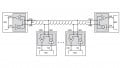
Microcontrollers only connect to the logic pins of a CAN transceiver, such as TXD, RXD, and STB; they do not interface with the actual CAN bus. So if your MCU uses a 3.3V logic supply, you can use CAN transceivers that reference its logic pins to a 3.3V supply while still working on a 5V CAN bus, such as the TCAN1042V or TCAN1051V. Pin 5 is the VIO pin, and applying 3.3V to this pin on these transceivers will allow the RXD, TXD, and STB/S pins to use 3.3V logic levels. Figure 2 shows this configuration.

Figure 2. CAN node with a 3.3-V MCU and 5-V CAN transceiver
Conclusion
Although it can seem confusing to think of CAN outside of the 5V realm, once you understand the functions of the different transceivers, choosing the right transceiver and calculating the power consumption caused by that transceiver can be easier.