Facebook
 Google
 GitHub
 Linkedin
Powering AI-RAN: How Telecom Power Architectures Must Evolve for the GPU Era
Accelerator-based computing brings faster load changes, higher current density, and tighter thermal constraints, requiring updates to rectifiers, DC/DC conversion, and battery backup.
Article co-authored by Francesco Di Domenico, Infineon
AI-RAN Creates a Power Paradox
AI-RAN makes the radio access network more adaptive. AI can help optimize radio resources, improve network operation, and support new applications at the edge. The same accelerator-based computing that enables these capabilities, however, changes how the baseband draws power.
Traditional baseband processing has comparatively predictable electrical behavior. In contrast, accelerator power use changes quickly. Inference tasks, AI models, and mixed workloads create sudden power shifts. These fluctuations cause wider load swings and higher heat. They also create heavy transient demands on the power delivery system.
You cannot solve this problem simply by increasing site power. Power systems designed for average demand often struggle during rapid changes. Load shifts can happen faster than control loops can adjust. They can also overload energy storage and thermal cooling systems.
AI-RAN deployments are still in their early stages. Public power data for complete systems is limited. Telecom sites differ from hyperscale AI data centers. However, both rely on similar accelerator hardware. Therefore, power solutions from AI servers offer valuable lessons for AI-RAN.
When Baseband Loads Become Dynamic
An accelerator does not draw constant power. Power demand changes based on workload types and task schedules. It also depends on hardware utilization and memory access. Power measurements show rapid variations even during steady workloads. For example, the power profiles in Figure 1 show rapid, workload-dependent variations in accelerator power demand.
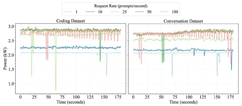
Figure 1. Measured power profiles for a Llama-3 70B online inference workload under sustained request rates. Image used courtesy of the National Laboratory of the Rockies
These power variations affect the entire site. A sudden power spike hits the low-voltage point-of-load rail first. The intermediate converter must instantly supply extra energy. The -48 V DC bus must stay stable. The rectifier must adjust without causing voltage drops. Finally, the cooling system must remove extra heat from outdoor or rooftop enclosures.
Even a small 70 W accelerator requires careful power design. Total board power includes the processor, memory, I/O interfaces, and conversion losses. It does not represent a single power rail. As accelerator capacity grows, managing low voltages, high currents, and fast load changes becomes the main technical challenge.
Keep the Telecom Backbone, but Reconsider Every Stage
The traditional telecom power architecture is still very effective. AC grid power feeds a rectifier that powers a nominal -48 V DC bus. This bus distributes power efficiently and supports battery backup. It also powers downstream DC/DC converters. AI-RAN does not require replacing this standard backbone. However, it does require some enhancements (Figure 2).
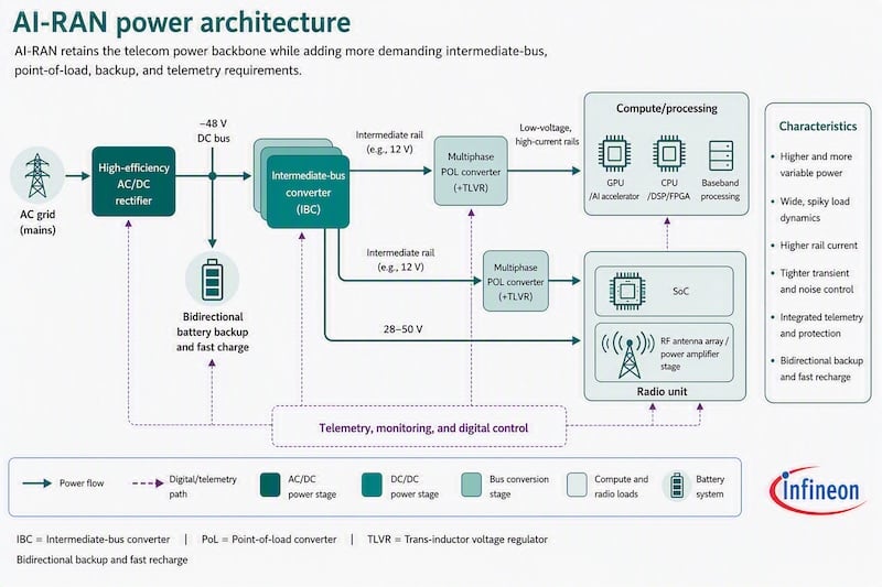
Figure 2. AI-RAN power architecture. AI-generated image from Infineon.
AI-RAN increases stress on every connected power stage. The AC/DC rectifier must stay efficient across a wider operating range. The intermediate-bus converter (IBC) must deliver power without overheating. Point-of-load (POL) converters must maintain stable voltages during fast current steps. The battery backup system must support higher and more variable loads without failing.
Real-time telemetry becomes essential. Operators should monitor rectifier loads, bus conditions, phase currents, battery status, and temperatures. A unified management layer displays this data. This allows engineers to fix electrical or thermal problems before outages occur.
Rectifiers Need Efficiency Across The Load Range
Telecom rectifiers vary widely in performance. Modern silicon designs already offer high efficiency. You do not always need to replace silicon. Instead, evaluate how efficiently a rectifier operates across real daily loads. Also check if it meets targets for power density, thermal performance, cost, and reliability.
Silicon (Si), silicon carbide (SiC), and gallium nitride (GaN) each offer specific benefits. Advanced silicon superjunction parts remain effective for high-voltage stages. SiC reduces switching and conduction losses at high voltages and high currents. GaN enables higher switching frequencies in suitable topologies and thermal layouts.
High switching frequency does not automatically mean better performance. A continuous-conduction-mode (CCM) totem-pole PFC may run at a lower frequency than a resonant design. Higher frequencies reduce the size of magnetic components. However, higher frequencies can increase switching losses, electromagnetic interference (EMI), and control complexity.
The EVAL_3K3W_TP_PFC_SIC2 design demonstrates one implementation approach. It is a 3.3 kW bidirectional totem-pole PFC using CoolSiC™ G2 and CoolMOS™ components with digital control. This PFC stage achieves 99.2% efficiency and 73 W/in³ power density in tests. Note that these numbers apply to the PFC stage, not the full power supply.
The REF-3K3W-HFHD-PSU reference design offers another option for testing high-frequency conversion. These reference designs help you test power topologies and semiconductor stress. You can also evaluate cooling needs and part-load efficiency before building a site.
Separate Intermediate-Bus And Point-Of-Load Conversion
The intermediate-bus converter (IBC) and point-of-load (POL) converter solve different problems. You should specify them separately.
The IBC steps down the 48 V DC bus to an intermediate rail, usually around 12 V. Design priorities include electrical isolation, efficiency, and power density. It must also offer good thermal performance and reliable operation across a range of input voltages.
A 1 kW quarter-brick implementation using XDPP1100 converts a 42 V to 60 V input to a 10 V to 15 V output. The documented design provides up to 80 A without heatsinks, with 97.3% peak efficiency and 564 W/in³ power density under the stated test conditions.
The POL stage converts that intermediate voltage into the low-voltage, high-current rails used by the accelerator. Here, transient regulation becomes dominant. A digitally controlled multiphase buck converter divides the load among several interleaved phases, reducing the current handled by each power stage, raising effective ripple frequency, and distributing heat across the board.
High-current delivery also depends on maintaining balanced phase currents during load changes. Infineon tests of a dual-phase design show closely matched phase currents during a 300 A load jump (Figure 3). This test does not simulate an explicit AI-RAN workload. However, it demonstrates the dynamic current sharing needed for modern processors.
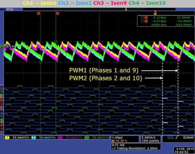
Figure 3. Phase-current balance across paired power stages during a 300 A load step. Image used courtesy of Infineon
Trans-inductor voltage regulation (TLVR) is an advanced feature for multiphase POL stages. TLVR magnetically couples the phase inductors together. This improves transient response and reduces the need for large output capacitors. It is very useful when board space, height, and cooling are limited.
Battery Backup Becomes an Active Power Stage
Higher site power reduces the backup duration if stored energy remains unchanged. Dynamic accelerator loads complicate battery discharge planning and thermal management. They also make it harder to decide which workloads to turn off during a blackout.
You can respond in three ways:
- Increase stored energy.
- Shed noncritical loads.
- Recover charge more rapidly after the event.
Most practical architectures will combine these approaches according to site criticality and outage history.
Bidirectional conversion turns the backup unit into an active participant in the power chain. The converter controls battery charging during normal operation and supports the DC bus during a disturbance. Relevant lessons can be transferred from AI-server battery-backup units, although telecom systems may require longer hold-up, different environmental qualifications, and field-serviceable battery arrangements.
Tee REF_48V_12KW_BBU_PPC_Si design demonstrates a modular 12 kW architecture using four parallel 3 kW power boards. It operates with a 36 V to 60 V battery range, regulates a 48 V output, and uses bidirectional partial-power conversion. The implementation includes OptiMOS™ MOSFETs, EiceDRIVER™ gate-driver ICs, protection circuitry, and system control. Its documented discharge efficiency exceeds 99% across the stated typical load profiles.
Five Priorities for Your AI-Ran Power Design
- Characterize dynamic behavior, not only average power. Capture load-step magnitude, slew rate, repetition, and simultaneous workload activity.
- Evaluate rectifier efficiency across the operating range. Peak efficiency alone does not reveal enclosure heat during lower or rapidly changing loads.
- Specify IBC and POL requirements separately. Bulk conversion and accelerator-rail regulation involve different topologies, control objectives, and transient constraints.
- Recalculate backup using realistic operating modes. Include accelerator power, cooling, conversion loss, load shedding, and recharge behavior.
- Coordinate power, thermal management, protection, and telemetry. Site-level visibility enables controlled responses before electrical or thermal limits disrupt service.
Conclusion
AI-RAN keeps the standard -48 V telecom power backbone. However, every connected stage must handle dynamic AI workloads. Wide-range rectifier efficiency, separated IBC and POL stages, multiphase control, and active battery backup are critical. These technologies ensure AI-RAN systems meet telecom standards for reliability, power density, and cooling.
Access Infineon’s AI-RAN hardware solutions to evaluate telecom rectifiers, intermediate-bus converters, multiphase controllers, and battery-backup designs for topology selection and benchmarking.
Feature image used courtesy of Adobe Stock
Related Content