Facebook
 Google
 GitHub
 Linkedin
Using Programmable Logic Devices for Systematic Power-Up Sequencing
Learn how single-chip programmable logic devices (PLDs) can replace multiple discrete components used in power-up sequencing circuits to save cost and PCB area.
Article co-authored by Gerardo Leyva-Hernandez, also of Texas Instruments
Many of today’s electronic products, regardless of how simple or sophisticated, require systematic power-up sequences that enable the product’s functions with the correct order and timing. If done incorrectly, the end result could range from a simple user inconvenience to catastrophic product failure.
Today’s electronics often use multiple discrete logic devices and passive components to accomplish power sequencing. Now, single-chip programmable logic devices (PLDs) integrate all of the necessary discrete components. In this article, we’ll focus on different power-rail sequences and timing using multiple inputs and outputs.
The Limitations of Using Discrete Solutions
Let’s begin by looking at Figure 1. This is a power-sequencing example based on a single-battery input.
It will help us understand how PLDs can simplify your designs while offering more flexibility compared to discrete logic solutions. If the battery voltage is acceptable, the device will proceed through the sequence based on the timing shown in the figure.

Figure 1. Power-sequencing example based on single-battery input. [click to enlarge]
Figure 2 is the circuit schematic for a discrete logic design that would generate the signals of Figure 1.

Figure 2. Analog and discrete logic power-sequencing schematic. [click to enlarge]
As you can see, supporting power sequencing through analog and discrete logic is easily accomplished. However, the number of devices and relative printed circuit board area are not optimal.
Inevitably, the discrete approach will lead to higher development costs and final product costs than a PLD-based design. Supporting analog and discrete logic also requires you to negotiate, procure, store, and place numerous discrete devices and their associated passives on the PCB.
Simplify Power Sequencing With Programmable Logic
The Texas Instruments (TI) TPLD1202 PLD is a single-chip solution that can meet the requirements of our example power sequence. This PLD includes up to 40 different logic elements and is easily configurable to support many applications.
TI’s InterConnect Studio design tool offers a drag-and-drop interface to design, simulate, configure, and program TI PLDs without coding. Figure 3 is a screenshot of InterConnect Studio and the power-sequencing circuit used to configure the TPLD1202 device.
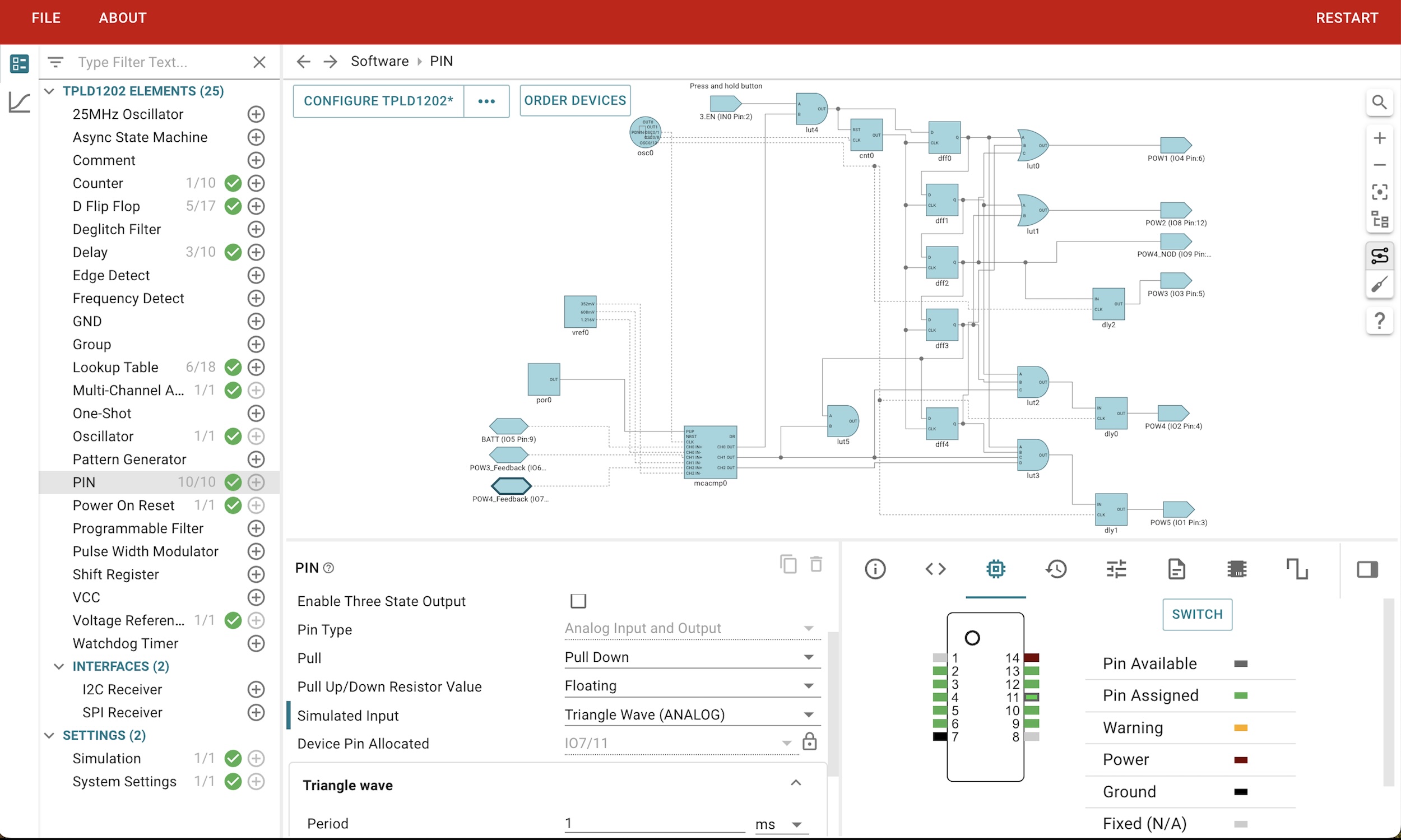
Figure 3. TPLD1202-based power sequencing through InterConnect Studio. [click to enlarge]
The circuit in Figure 3 uses an input-enable signal fed into a counter. The control data of the counter block, combined with the clock from the internal oscillator, sets the delay between each sequence signal. Since the counter reset triggers on the rising and falling edge of the enable signal, the device does not signal to begin power down until the input enable signal falls.
What if we wanted to change the timing of the power-sequencing controller? Using a discrete resistor-capacitor network would require new RC values and a change to our bill of materials. With a PLD design, we could simply reconfigure the internal oscillator and associated dividers without needing to modify the bill of materials.
Powering Additional Voltages Up and Down
Because the example application relies on a battery for its power source, the voltage can vary based on the state of the battery. Building on the previous example, you can use the additional logic functions to add another power-sequencing use case.
In Figure 4, the TPLD1202 is looking for a voltage or voltage range on POWER3 feedback before enabling POWER3. Then, it moves on to the POWER4 feedback to check its requirements against the battery voltage (Figure 4). Only after meeting these voltage requirements will the product fully power up for operation.
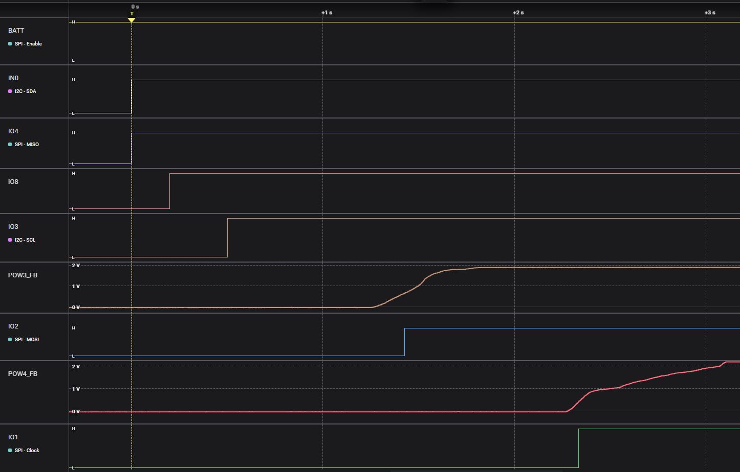
Figure 4. TPLD1202 power sequencing with voltage monitoring. [click to enlarge]
For power-down sequences, you can ensure safe power-down by using the same parameters monitored during power-up in reverse.
Tables 1 through 3 outline the savings realized when using TI PLDs for power sequencing. For a starting reference, Table 1 identifies the 19 discrete components and their package sizes.
Table 1. Discrete logic bill of materials
| TI device | Quantity | Description | Package (mm2) | Extended package (mm2) |
| LM555 | 1 | Oscillator | 9 | 9 |
| LM393B | 3 | Comparator | 4 | 12 |
| SN74HC04 | 1 | 6-channel inverter | 32 | 32 |
| SN74HCS574 | 1 | 8-channel D-type flip-flop | 11 | 11 |
| SN74HC74 | 1 | 2-channel D-type flip-flop | 32 | 32 |
| SN74HC32 | 3 | OR gate | 32 | 96 |
| SN74HC08 | 7 | AND gate | 32 | 224 |
| CMHSH5-2L | 2 | Schottky diode | 6 | 12 |
| Total | 19 | 158.25 | 428 |
As shown in Table 2, we can use a single PLD with a package size smaller than each of the 19 individual discrete components.
Table 2. Programmable logic bill of materials
| TI device | Quantity | Description | Package (mm2) | Extended package (mm2) |
| TPLD1202RWBR | 1 | PLD | 2.56 | 2.56 |
Finally, Table 3 shows the reductions in the bill-of-materials and the PCB area. A single TI PLD can translate into PCB space savings of over 99% and PCB cost savings of over $1 compared to discrete logic designs.
Table 3. PCB area comparison
| Benefit | Discrete logic devices | TPLD1202 | PLD savings |
| Bill of materials (quantity) | 19 | 1 | 95% |
| PCB area (extended package) (mm2) | 428 | 2.56 | 99% |
Further savings can be realized by eliminating the procurement costs needed to obtain an additional 19 devices. For simplicity, we did not include passive components in our comparison, but you can also expect savings of as much as 90% on the passives needed for a TI PLD design.
Other PLD Use Cases
PLDs offer configurable logic with both digital and analog functions, popular interfaces, and integrated features such as oscillators that can optimize your design for:
- Functionality.
- Bill of materials.
- PCB area.
- Procurement costs.
- Manufacturing costs.
PLDs also do not have the overhead associated with competing solutions such as field-programmable gate arrays. TI’s PLDs are simple to configure and program because you don’t need any experience with hardware description languages to use InterConnect Studio.
These PLDs benefits also make them suitable for input/output expansion, sensor interfaces, LED control, and voltage monitoring.
All images used courtesy of Texas Instruments.