 Facebook
 Google
 GitHub
 Linkedin
Failures in Electronic Systems Can be Catastrophic. How Can We Avoid Them?
Rocket Lab’s recent in-flight failure was the result of an electrical system failure. This evokes the question, How can electrical failures be avoided?
On July 4th, Rocket Lab launched its electron rocket for its 13th mission—this time, carrying a payload of seven different satellites.
The launch began successfully as the rocket proceeded through a number of stages as planned: the nominal Stage 1 engine burn, Stage 1–2 separation, Stage 2 ignition, and the fairing jettison. Dramatically, several minutes into the second stage burn, the engine shut down and the rocket failed to reach orbit, resulting in the subsequent loss of the rocket and its payload.

Rocket Lab Electron’s July 4 launch. Image used courtesy of Universe Today
Only recently has the source of the failure been identified as a faulty electrical connection.
Rocket Lab explains that the connection was intermittently secure through the flight, creating a resistance that caused heating and thermal expansion in the component. This heat caused surrounding components to melt, disconnect, and eventually fail. The issue evaded detection pre-flight as the intermittent connection was solid during the testing.
Electrical Failures: Why Do They Happen?
Such a catastrophe evokes the question, How can engineers avoid failures in their system designs?
The answer is not straightforward. No matter how thorough you are, anomalous events can happen like in the case of Rocket Lab.

Extreme example of an electrical failure. Image used courtesy of Tempo Automation
In general, failures in electrical systems are often caused by inadequate design, such as improper component selection or inappropriately sized interconnects. Errors can also crop up in the manufacturing and assembly steps, such as faulty connections or contamination.
For the sake of this article, we’ll be discussing some design-side modes of failure.
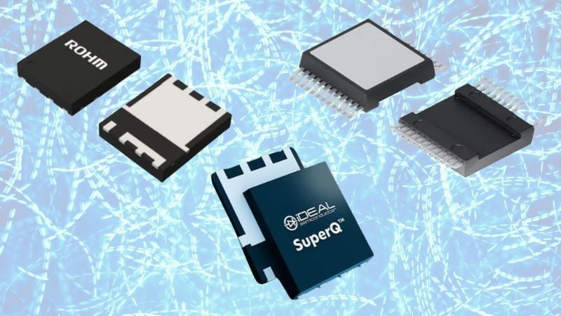
Component Selection Considerations
When choosing components in a PCB, it's vital that designers consider the tolerance of the component. Every electrical component has a defined operating range—the maximum/minimum values for current and voltage inputs and operating temperatures. When components are not carefully selected and integrated within these ranges, failures are likely to occur, normally in the form of overheating.
All electronic components also have a value tolerance. For example, the datasheet for a 1 uF capacitor will often say something like ±20%. This indicates that because of manufacturing variances, your capacitor can actually be anywhere from .8 uF to 1.2 uF. This becomes very important when designing something like an AC-DC converter where ripple voltage is an important specification that is directly influenced by the capacitor’s actual value.

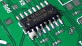
Device ratings of Micrel's IttyBitty RC timer IC, the MIC1555/1557. Image used courtesy of Micrel (Microchip)
Engineers must account for these tolerances during both the manufacturing and operation of their systems. For this reason, cautious engineers will design their systems with a factor of safety, giving them wiggle room should something anomalous occur to the system.
Interconnect Design Considerations
Another common mode of failure in a PCB or a chip is inadequately designed interconnects.
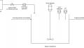
In a PCB it is important to properly size traces based on the current capacity, spacing between traces, and the size and pitch of the pads that the traces connect to. Traces can be thought of like any other electrical component; when their tolerances are exceeded, they will overheat and fail.
There are a variety of PCB trace width calculators freely available to engineers that account for all of these factors.

Graphic showing results of electromigration. Image used courtesy of Synopsys
In chip design, electromigration can be a major failure mode. Electromigration is the movement of metallic atoms in an IC interconnect caused by high current densities. This results in either the deposition of atoms (called Hillocks), which leads to shorts, or the depletion of atoms (called Voids), which results in opens.
Like PCB trace width failures, electromigration leads to failures at high current densities, meaning that a simple way of avoiding the issue, amongst other methods, is to widen the wire to decrease current density. Inappropriately-sized interconnects will lead to system failures via electromigration.
Two of Many Fail-Safes
While we only touched on two very basic modes of failure in electrical systems, they are important to know. Both improperly-selected components and improperly-sized interconnects are common yet avoidable modes of electrical failure.
How else do you avoid failures in electronic systems? Share your thoughts in the comments below.
Related Content


This is a fascinating area of interest at all levels of system design. I find it useful to constantly change my viewpoint from electrical to mechanical to chemical and to environmental, to have a better chance of revealing a weakness. There are usually simple ways to provide some redundancy to better handle both known and unforeseen failure modes. I hope more articles are on the way.