Facebook
 Google
 GitHub
 Linkedin
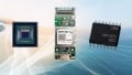
New Proximity Sensor from Vishay Targets Consumer and Industrial Applications
This article takes a deeper look at the technical concepts at play in a specific proximity sensor, the VCNL36821S from Vishay.
The VCNL36821S uses infrared signaling, has on-chip digital signal processing, and communicates via I2C.
Optical Distance Detection
The basic premise of sensors such as the VCNL36821S is that infrared light is emitted by the device, reflected off the surface of some object, and detected by the same device. The reflected light is converted into a current, and the amplitude of this current becomes a means of measuring the distance between the sensor and the object.
Noise and Interference
Infrared light is used because it is easier to separate from the visible light that will be present in most application environments. However, infrared isn’t an immediate solution to the problem of optical interference: light from the sun and from incandescent bulbs contains energy at infrared wavelengths.
However, these light sources tend to produce fairly steady levels of illumination, and any significant changes in intensity will be slow and irregular. Thus, we can further separate infrared signals from ambient radiation by incorporating high-frequency variations. Television remote controls, for example, encode information into a high-frequency carrier wave:

Diagram taken from a Texas Instruments app note on infrared remote control implementation.
The VCNL36821S, on the other hand, can achieve adequate performance simply by generating pulses of light with a programmable width of 50–400 µs and a programmable period of 10–80 ms. (The detector automatically updates its signal processing behavior in accordance with the characteristics of the pulsed light produced by the emitter.) I like that this device offers wide customization ranges; it seems that this feature would give the designer some additional ability to overcome application-specific noise or interference sources.
Another source of problematic IR light is the emitter itself. When transmission and reception devices are housed in the same package, a transparent cover placed near the surface of the device can reflect some light directly from emitter to detector. The following diagram helps to convey how this occurs, and it also depicts the optical angle that Vishay considers acceptable for most VCNL36821S applications.

Diagram taken from Vishay’s VCNL36821S app note, which is an excellent resource for anyone who wants further information on this sensor.
This reflection creates an offset that the VCNL36821S can automatically subtract from the proximity measurements by means of the “PS_CANC” (CANC stands for “cancellation”) registers.
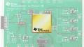
System-on-Chip Proximity Sensing
The VCNL36821S integrates an IR emitter, an IR detector, analog signal conditioning, analog-to-digital conversion, digital signal processing, and standardized digital communication into a 2.55 × 2.05 mm surface-mount package.

Block diagram of the VCNL36821S taken from the datasheet.
It really does seem like Vishay has incorporated a great deal of functionality that will help engineers to implement robust proximity sensing without excessive design effort. As shown in the next diagram, few external components are needed, and connection to the system’s microcontroller or digital signal processor is straightforward.

Hardware pin connection diagram taken from the VCNL36821S datasheet. I’m not sure why the processor is labeled “baseband.”
Window Detection
The VCNL36821S includes a feature that corresponds to an important general concept in sensor applications. The idea is that measurements are compared to an upper threshold and a lower threshold, and these two thresholds create ranges of measurement values that will or will not provoke some sort of response from the processor.
I call this “window detection” because it allows you to configure a system such that it takes action only when sensor data is inside or outside of a specified measurement window. An interrupt-based window detection scheme is highly efficient, because the processor gets involved only when window detection indicates that some sort of action is required.
Let’s consider a temperature-monitoring device. Most of the time, the measured temperature is in the “acceptable” range—0°C to 70°C, for example. If the temperature is too high or too low, the system’s microcontroller must deactivate a sensitive piece of equipment. Dedicated hardware compares each reading to the upper and lower thresholds that delimit the range of acceptable temperatures, and the processor is notified (via an interrupt) only when the reading is outside of the window.
This type of interrupt scheme can be implemented in proximity-sensing applications by means of the VCNL36821S’s interrupt output pin in conjunction with the upper threshold (PS_THDH) and lower threshold (PS_THDL) registers.
What kind of applications have you found for optical proximity sensing? Feel free to share some experiences or advice in the comments section below.
Related Content