
New Quad-output DC-DC Regulators from Analog Devices Can Be Paralleled for 4.8A
The LTM4668 and LTM4668A accept 2.7V to 17V inputs and produce four parallelable 1.2A outputs.
The new µModules from Analog Devices incorporate all the necessary inductors, power FETs, switching controllers, and support components into 6.25mm x 6.25mm x 2.1mm BGA packages.
The LTM4668 and the LTM4668A produce output voltages in the range of 0.6V to 1.8V and 0.6V to 5.V, respectively. The units are pin-for-pin compatible with each other.
For applications that demand more than 1.2A, the four sections of the quad µModules can be paralleled, supplying up to 4.8A.

LTM4668A. Image from Analog Devices
The only external components required are the bulk input and output capacitors and the resistors that set output voltages. By replacing so many separate components with one very small package, the new devices will likely simplify manufacturing and reduce both board space and BOM requirements.
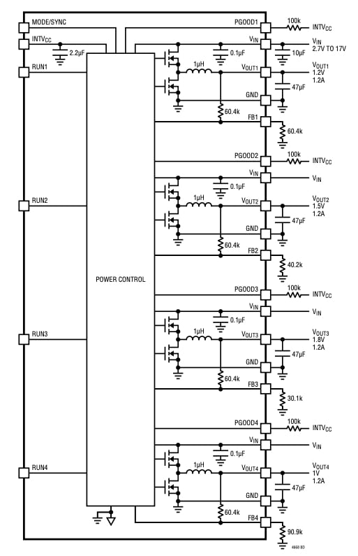
Block diagram of LTM4668. Image from Analog Devices
ADI believes that this will make the new µModules a great choice for OEMs building telecom, networking, and industrial applications.
Typical Application
In a typical application of the LTM4668A, the resistors attached to points VFB1 through VFB4 determine the output voltages.

Typical application of LTM4668A; 5V to 17V input, quad 1.5V, 1.8V, 2.5V, and 3.3V. Image from Analog Devices
The picture is similar for the LTM4668.
Frequency Synchronization
Aside from output voltage ranges, the principal difference between the devices is the typical switching frequencies of 1.0MHz for the LTM4668 and 2.25MHz for the LTM4668A. For applications with switching noise sensitivity, both μModules can be synchronized to an external clock.

LTM4668A. Image from Analog Devices
Acceptable frequency ranges for the LT4668 are from 500kHz to 1.5 MHz; for the LT4668A, frequency ranges span from 1.5MHz to 3MHz.
Burst Mode Operation
During periods of low load demand under burst mode operation, the power MOSFETs operate only intermittently. This is an important capability for applications where power conservation is a key design goal.
In sleep mode, the device partially shuts down because the very light load needs are satisfied by the charge of the output capacitor. If all four channels are in sleep mode, the µModule draws only 8µA.
Pulse-skipping Mode Operation
Pulse-skipping mode operation may be appropriate for applications in which intermediate currents are desired and where low output ripple is paramount.

Burst mode operation and pulse-skip mode efficiency; VIN = 12V, VOUT = 1.5V, fS = 1MHz. Image from Analog Devices
This method does sacrifice some efficiency when compared to burst mode.
Multi-channel Parallel Operation
As described, it is possible to combine the four sections to produce a 4.8A output. Two sections can be combined to produce 2.4A, and the two other sections can be combined to produce another 2.4A output. Or, three can be combined to produce 3.6A, leaving the last as a 1.2A output.

2+2 and a 4-channels parallel concept schematics for clock phasing. Image from Analog Devices
In the example illustrated on the top of the above image, creating two 2.4A outputs involves channel 1 controlling channel 2 and channel 4 controlling channel 3. Below, channel 1 controls the other three channels to effect a 4.8A output.
Evaluation Kit and Demo Manual
Analog Devices offers the DC2785A-A, an evaluation kit for the LTM4668 µModule. The company describes it as “an easy way to evaluate the performance of the LTM4668.”

The DC2785A-A. Image from Analog Devices
It also offers a demo manual to be read in conjunction with the LTM4668 datasheet.
Around the Industry
Texas Instruments offers its LP8758-E0, a quad converter with an input voltage range of 2.6V to 5.5V. Output voltages from 0.6V to 3.36V are also possible with an output current of 4A.
The MAX77812 from Maxim offers four outputs with a total maximum output of 20A. The input voltage range is 2.6V to 5.5V, and the output can range from 0.250V to 1.525V in steps of 5mV.


