Facebook
 Google
 GitHub
 Linkedin
Time-To-Digital Converters Emerge as Key Components in Autonomous Vehicles
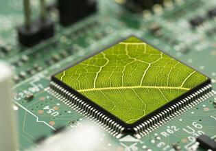
See how advancements in resolution and power consumption spur new applications in flow meters and LIDAR.
Advancements in resolution and power consumption spur new applications in flow meters and LIDAR.
A Look Inside Time-to-Digital Converter Applications
Water Flowmeters
Water flowmeters include two sound transducers, “A” and “B,” as in the picture below. Either can be used to transmit or detect a sound pulse.

Water Flowmeter. Image source: Maxim integrated
First “A” transmits, and “B” receives, with an appropriately configured time-to-digital converter recording the time between transmission and reception. Then, the sequence is reversed, with “B” transmitting and “A” receiving. This time interval, too, is captured by the time-to-digital converter.
It may seem that the times would be equal, as the sounds are traveling the same distance, but it isn’t so. The sound is moving through the water, but the water itself is traveling. So the sound going against the flow is slowed down, and the sound going with the flow is sped up.
The time periods are both noted, and by observing which time is longer and which is shorter, the device easily determines the direction of water flow. Additional knowledge of factors, such as the water pipe’s diameter, allows simple calculation of the volume of water flow.
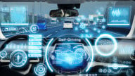
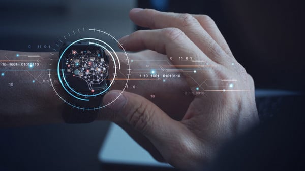
Smart Cars
LIDAR stands for Light Detection and Ranging. It is a key component in smart cars, because it can warn the driver, or an autonomous controller, when a vehicle is getting too close to an object such as a barrier or to another vehicle.
Lidar works by emitting a laser pulse, and noting the arrival of the same pulse when it returns to the source.
Here, too, the time is noted by the time-to-digital converter. The speed of the pulse is the speed of light. With time and velocity known, the device can easily compute the distance between objects.
Improving Time-To-Digital Conversion
Since light travels at 300,000,000 meters per second, it will travel 1 meter in 3.3 x 10⁻⁹ seconds. A clock period of 3.3 ns corresponds to a clock frequency of 300 MHz, which is doable with today’s technology.
However, for the sake of avoiding motor vehicle collisions, resolutions more on the order of 0.1 meters are more practical. Ten times the resolution calls for ten times the clock speed, and a digital system clocked at 3.0 GHz is pushing it.
A common architecture employed in time-to-digital converters is diagrammed below.

Common time-to-digital architecture. Image source: ams.
REFCLK is a relatively slow clock. tstop is an internal measurement made very locally within the time-to-digital converter (TDC). tstop is the time, relative to the last REFID pulse, that a measurable event has occurred.
The number of REFID pulses are counted, and they are multiplied by the period of the REFID. They are added to tstop. Thus, the time period between when a LIDAR pulse, as an example, is emitted and when it is received after it bounces back is ascertained. Multiplying by the speed of light and dividing by two gives the distance.
While very high-speed elements are needed within the TDC, the system as a whole does not need to be clocked at an enormous rate.
The AS6500 from ams
The ams AS6500 is a four channel time-to-digital converter (TDC) that was designed with LIDAR applications for vehicles, drones and robots in mind. The unit can measure down to 1 cm, beating 0.1 meters by a factor of 10. It can make 1.5 million measurements each second, and can create a virtual picture of any threat a vehicle might face.

The AS6500 from ams. Image Source: ams.
The AS6500 works with a 3.3 V power supply, with active power dissipation of 60 mW, and only 60 μA on standby. The device comes in a QFN40 package that measures 6 mm × 6 mm.
AMS also offers a development kit, the AS6500-QF_DK, to help designers to reduce time to market for their AS6500-based projects. The kit includes programming and GUI software for PCs, enabling users to configure and connect their Start and Stop signals and begin taking sample time measurements within minutes.
The MAXREFDES70# from Maxim
The MAXREFDES70# is a waterflow meter. Because of the device's very low power consumption, it will operate for 20 years without a battery replacement.

The MAXREFDES70# from Maxim Integrated
Before time-to-digital-converters came to be utilized in flowmeters, mechanical devices were employed, subject to all the reliability issues associated with devices composed of moving parts.
The heart of the MAXREFDES70# is Maxim’s MAX35101 time-to-digital converter. This device can measure time periods ranging from 20ps to 8ms. It can operate from a single 2.3 V to 3.6 V power supply. Designers will appreciate the on-board 8 KB flash memory for data logging.
The device comes in a 5mm x 5mm, 32-Pin TQFP Package, and operates over a -40°C to +85°C temperature range.
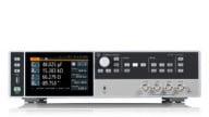
The TDC7200 from Texas Instruments
The TDC7200 from Texas Instruments is another example of an electronic stopwatch. It has two range modes, 12 ns to 500 ns and 250 ns to 8 ms. In either mode, it has five stops, so the user can compare up to five intervals, as illustrated in the diagram below:

The TDC7200. Image source: Texas Instruments
The device comes in a 5.00 mm by 4.40 mm package, operates over a temperature range of –40°C to 85°C, and consumes as little as 0.5 μA.
The TDC7200 was designed with both LIDAR and flow measurement in mind. When the unit is combined with the TDC1000 analog front end and the MSP430 low power MPU, the designer has the basis of what TI calls “a complete TI ultrasonic sensing solution.”
The TDC7200EVM is a module that allows users to evaluate the operation and performance of the TDC7200 Time-to-Digital Converter. It comes with a user-friendly Graphic User Interface (GUI) to help designers get their product to market as quickly as possible.
What's your experience with time-to-digital converters? Let us know in the comments.