Facebook
 Google
 GitHub
 Linkedin
Arduino-Compatible RS-485 Linear Hall Sensor Board for Magnetic Field Sensing
This project brief describes how to build and use an Arduino-compatible board that reads a linear Hall-effect sensor and reports the measurement over an RS-485 bus.
The RS-485 Linear Hall Sensor Interface Board is an Arduino-compatible module built around an ATmega328 microcontroller. It combines two Texas Instruments products: a SN65HVD08DR half-duplex RS-485 transceiver with a DRV5053 linear Hall-effect sensor on a single board. This creates a self-contained node that measures magnetic fields and reports data over an industrial RS-485 network.
Header connectors break out multiple I/O lines, and the board includes a footprint for an optional 0.96-inch OLED display. This makes it useful as both a sensor node and a general-purpose RS-485 development platform. Figure 1 shows the assembled board.
A simple, practical application is an ON/OFF control system that operates over RS-485. Screw terminals handle the RS-485 A and B twisted-pair connections. All other signal lines break out onto 2.54 mm header connectors for easy interfacing with other boards, sensors, or an Arduino programmer.
The DRV5053 Hall sensor outputs an analog voltage proportional to magnetic field strength and polarity. The onboard ATmega328 reads this voltage on an analog input and transmits the value over the RS-485 bus, allowing the reading to be monitored or acted on remotely. In tests, the sensor produced ADC readings of roughly 6 for the south pole, 220 for centered (no field), and 440 for the north pole.
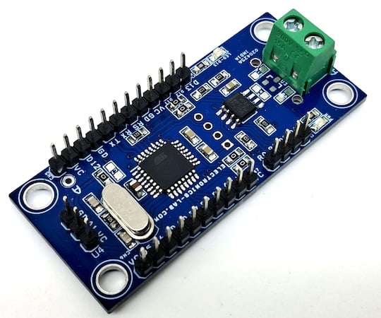
Figure 1. The assembled RS-485 Linear Hall Sensor Interface Board.
Specs and Features
- Supply voltage: 5 V DC
- RS-485 communication, half-duplex, via SN65HVD08DR transceiver
- Screw terminal for RS-485 A/B connection
- ATmega328 microcontroller, Arduino-compatible
- Dedicated programming and bootloader connector (CN4)
- Onboard linear Hall-effect sensor: DRV5053
- DRV5053 ADC output: 6 (south pole) – 220 (centered) – 440 (north pole)
- Onboard power LED and function LED (connected to D13)
- Optional 0.96-inch OLED display footprint (I2C, underside of PCB)
- Optional 433 MHz ASK RF module footprint
- Multiple general-purpose I/O lines broken out on headers
- 4 mm mounting holes at all four corners
- PCB dimensions: 60.33 mm x 26.51 mm
How It Works
The SN65HVD08DR is a 3.3 V to 5.5 V RS-485 transceiver. It combines a three-state differential line driver and receiver in a single SOIC-8 package. It meets ANSI TIA/EIA-485-A and ISO 8482 standards and draws less than 90 mW of quiescent power. As a 1/8 unit-load device, it supports up to 256 nodes on a single bus.
On this board, the ATmega328 controls the transceiver directly. Pin RO connects to Arduino D10, RE to D2, DE to D3, and DI to D11. This gives the microcontroller full control over transmit and receive directions.
The DRV5053 is a chopper-stabilized, linear Hall-effect IC. Its analog output swings from 0 V to 2 V based on magnetic flux density. It also indicates field polarity. The device operates from 2.7 V to 38 V with reverse-polarity protection down to -22 V. The CA variant used here has a sensitivity of 23 mV/mT. The ATmega328 samples this output on analog input A1 and packages the reading for transmission over RS-485.
Firmware for testing the board is provided as example Arduino code. The board is designed to pair with a previously published RS-485 relay board. After uploading the transmitter code and setting a threshold, the relay trips automatically once the Hall sensor reading crosses that mark. Programming and bootloading use the dedicated CN4 header, which wires to an external Arduino Uno as shown in the Connections section.
Schematic and Bill of Materials
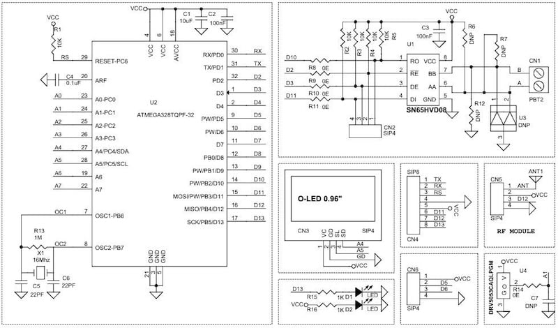
Figure 2. Schematic of the RS-485 Linear Hall Sensor Interface Board.
The bill of materials is shown in Table 1.
Table 1. BOM for RS-485 Linear Hall Sensor Interface Board
| REF | DESCRIPTION | QTY | MFG | SUPPLIER | PART NO. |
| ANT1 | ANTENNA - OPTIONAL | 1 | |||
| CN1 | 2-Pin Screw Terminal, 5.08 mm Pitch | 1 | Phoenix | DigiKey | 277-1247-ND |
| CN2, CN3, CN5, CN6 | 4-Pin Male Header, 2.54 mm Pitch | 4 | Wurth | DigiKey | 732-5317-ND |
| CN4 | 8-Pin Male Header, 2.54 mm Pitch | 1 | Wurth | DigiKey | 732-5321-ND |
| C1 | 10 uF / 16 V Ceramic, SMD 0805 | 1 | Yageo/Murata | DigiKey | |
| C2, C3, C4 | 100 nF / 50 V Ceramic, SMD 0805 | 3 | Yageo/Murata | DigiKey | |
| C5, C6 | 22 pF / 50 V Ceramic, SMD 0805 | 2 | Yageo/Murata | DigiKey | |
| R6, C7, R12, R7 | DNP | 4 | |||
| D1, D2 | LED, Red, SMD 0805 | 2 | Osram | DigiKey | 475-1278-1-ND |
| R1, R2, R3, R4, R5 | 10K 5%, SMD 0805 | 5 | Yageo/Murata | DigiKey | |
| R8, R9, R10, R11, R14 | 0R 5%, SMD 0805 | 5 | Yageo/Murata | DigiKey | |
| R13 | 1M 5%, SMD 0805 | 1 | Yageo/Murata | DigiKey | |
| R15, R16 | 1K 5%, SMD 0805 | 2 | Yageo/Murata | DigiKey | |
| U1 | SN65HVD08, SOIC-8 | 1 | TI | DigiKey | 296-39173-1-ND |
| U2 | ATmega328, TQFP-32 | 1 | Microchip | DigiKey | ATMEGA328-AU-ND |
| U3 | SM712 - Do Not Install | 1 | |||
| U4 | DRV5053CAQLPGM | 1 | TI | DigiKey | 296-DRV5053CAQLPGMTB-ND |
| X1 | 16 MHz Crystal | 1 | ECS Inc | DigiKey | X1103-ND |
Connections
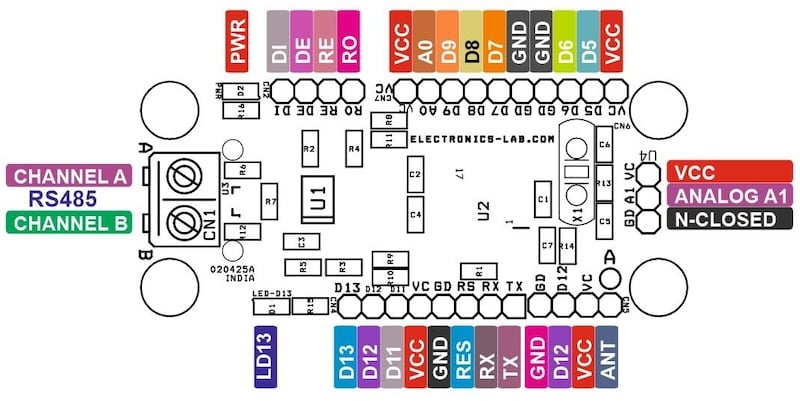
Figure 3. Connector and pin locations on the RS-485 Linear Hall Sensor Interface Board.
CN1 — RS-485 Screw Terminal (2-pin, 5.08 mm pitch):
- Pin 1 = RS-485 Channel B
- Pin 2 = RS-485 Channel A
CN2 — Optional Header (4-pin, 2.54 mm pitch):
- Not used in the standard configuration
CN3 — OLED Display Header (4-pin, 2.54 mm pitch, I2C):
- Pin 1 = VCC
- Pin 2 = GND
- Pin 3 = SLA (SCL)
- Pin 4 = SDA
CN4 — Programming/Bootloader Header (8-pin, 2.54 mm pitch):
- Pin 1 = TX
- Pin 2 = RX
- Pin 3 = Reset
- Pin 4 = GND
- Pin 5 = VCC
- Pin 6 = D11
- Pin 7 = D12
- Pin 8 = D13
CN5 — RF Module Header (4-pin, 2.54 mm pitch, optional 433 MHz ASK):
- Provision for an optional 433 MHz ASK RF module
CN6 — I/O Header (4-pin, 2.54 mm pitch):
- Pin 1 = VCC
- Pin 2 = D5
- Pin 3 = D6
- Pin 4 = GND
CN7 — I/O Header (6-pin, 2.54 mm pitch):
- Pin 1 = VCC
- Pin 2 = A0
- Pin 3 = D9
- Pin 4 = D8
- Pin 5 = D7
- Pin 6 = GND
U4 — Magnetic Sensor Header (DRV5053):
- Pin 1 = VCC
- Pin 2 = Analog A1
- Pin 3 = GND
Indicator LEDs:
- D1 = Function LED, connected to D13
- D2 = Power LED
Arduino Programming and Bootloader
The board is bootloaded and programmed through CN4 using an external Arduino Uno as an ISP-style programmer. Wire the Uno's D13, D12, and D11 to the matching pins on CN4, connect 5 V and GND, and tie the Uno's RESET, RX, and TX lines to CN4's Reset, RX, and TX pins as shown in Figure 4. This setup lets the Arduino IDE bootload the ATmega328 and upload firmware directly to the board.
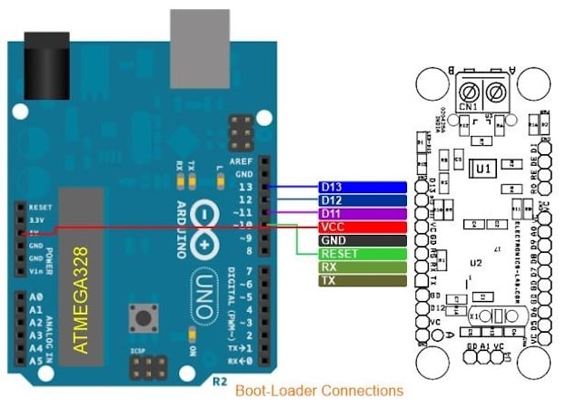
Figure 4. Wiring an Arduino Uno to CN4 to bootload and program the board.
PCB and Code Files
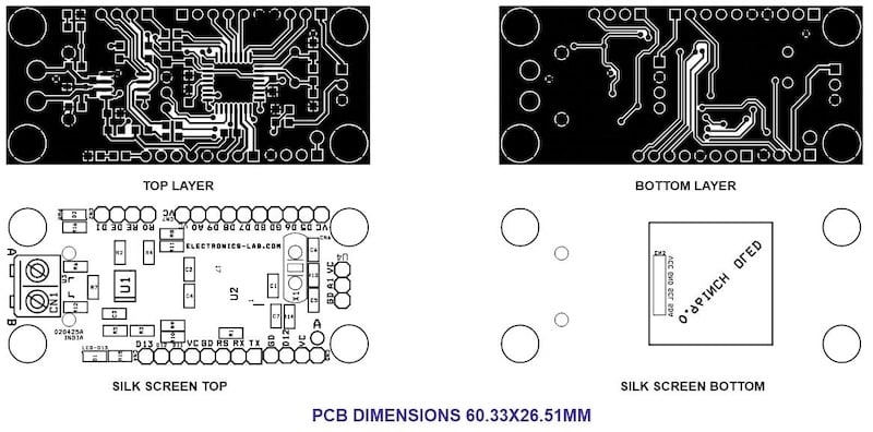
Figure 5. PCB layout of the RS-485 Linear Hall Sensor Interface Board, showing the top and bottom copper layers and silkscreen.
You can download the layout files for this project here:
RS-485 Linear Hall Sensor Interface Board Gerber Files
You can download the code for this project here:
RS-485 Linear Hall Sensor Interface Board Code
Except where noted, all images used courtesy of Rajkumar Sharma
Related Content