 Facebook
 Google
 GitHub
 Linkedin
Build a Desktop Industrial Automation Trainer
In this project, the reader will learn how to build and program a desktop industrial automation trainer for experimentation in robotics, motor, and process control system concepts on their workbench.
Robotics and industrial automation are two hot topics in the Career and Technical Education community.
The cost of industrial training systems ranges from as low as a hundred dollars up to hundreds of thousands. As an Industrial Electrical-Electronics and Maintenance instructor, I encouraged my students to perform outside lab experiments to foster the continual practice of technical concepts and principles taught in the classroom. Additionally, continual hands-on learning will improve technical skills and knowledge tenfold. In this project, you will learn how to build a very low-cost desktop industrial automation trainer to conduct your own experiments in robotics, as well as motor and process control systems on the workbench. The key components to building the Desktop Industrial Automation trainer are shown next.

Figure 1. Block diagram for Desktop Industrial Automation trainer.
Parts List
- Arduino Uno or equivalent microcontroller development platform
- Velocio Ace PLC
- Velocio 5A Relay Terminal Block
- Wall plug - 5V, 2A
- simulation stick
- small dc motor
- solderless breadboard
- jumper wires
- vBuilder software
What is a Programmable Logic Controller (PLC)?
A Programmable Logic Controller or PLC is basically an industrial computer used in home and manufacturing applications. Like an ordinary computer, the PLC has a CPU (Central Processing Unit) and internal memory to store programs. Aslo, PLCs have power supplies to operate their internal circuits and mermory devices. Unlike the ordinary computer, the PLC can control large industrial machines and processes using electromechanical relays and triacs. A triac is a bidirectional AC switch capable of operating high current devices like AC motors, incandescent lamps, and solenoids up to 5A (amperes). Also, the PLC has a chassis or rack to hold various Input-Output (I/O) wiring modules. The rack is made from a metal frame. Mounted to the metal frame is a printed circuit board with electrical connectors soldered to it. Software data and electrical control signals are transfer from the I/O wiring modules to the PLC's CPU for processing. The I/O wiring modules allow a variety of electrical and electronic sensing devices and loads to easily be attached to the PLC. A terminal block attached to the I/O wiring module allows electrical switches, sensors, motors, solenoids, and incandescent lamp devices to be wired to the PLC. Figure 2 shows a typical PLC with a power supply and I/O wiring modules. To learn more about triacs, check All About Circuits' chapter on this thyristor component.
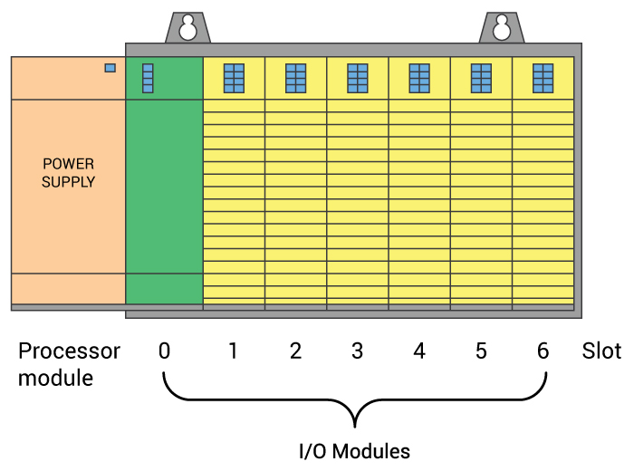
Figure 2. A typical PLC
Ladder Logic Programs and Relay Ladder Diagrams
To program an application using a PLC traditional coding languages like C, C++, or Python are not required. The PLC uses a unique programming language that is graphical. Each bit instruction of the PLC application program represents a physical electrical-electronic component and its operating trigger or state. The bit instructions are placed on a line call a rung. All rungs are then attached to each other using side rails. The final collective group of rungs and rails makes up what is called a Ladder Logic program. Figure 3 shows an example PLC Ladder Logic Program.

Figure 3. An example of a basic Ladder Logic Program
As shown in the example of Figure 3, the bit instructions are the pressure, temperature, and manual pushbutton switches, as well as the starter coil. Rungs are built using bit instructions wired on horizontal lines. The two vertical lines are the rails. Ladder Logic programs are derived from the old relay ladder diagrams that were used in old industrial control systems for various manufacturing production and processing operations. An example of a relay ladder diagram is shown in Figure 4. The industrial machine's intelligence is based on the arrangement of the electrical or electromechanical device switching contacts. Basic digital gate functions like AND, OR, and NOT logic circuits can be built using electrical switches, electronic sensors, and electromechanical relay contacts. A combination of these basic logic functions allows for more complex machine control operations to be built. For additional information on PLCs and Ladder Logic programming, check out All About Circuits' Chapter 6, "Ladder Diagrams".
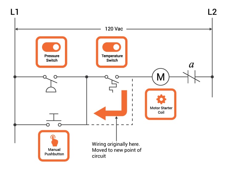
Figure 4. An example of Relay Ladder Diagram
Building the Desktop Industrial Automation Trainer
With a basic understanding of what PLCs, Ladder Logic programs, and Relay Ladder Diagrams are, you are ready to build your Desktop Industrial Automation Trainer. As shown in the Parts List and the Block Diagram trainer is made using low-cost components. The main components of the trainer are the Velocio Ace PLC and the 5A Relay Terminal Block. The additional components consisting of the Arduino Uno and Simulator stick will allow you to explore the fundamentals of Ladder Logic programming using vBuilder software. The assembly of the Desktop Industrial Automation Trainer is quick and easy. The first version of the trainer consists of inserting the Simulator stick into the input digital port of the Ace PLC. The Simulator stick has 6 toggle switches that will provide digital input signals to the Ace PLC to process and operate the 5A Relay Terminal block. The terminal block has 6 industrial grade electromechanical relays to control both AC and DC electrical- electronic loads using SPST (single pole-single throw ) contacts. The 5A Relay Terminal Block has a small electrical wiring harness that needs assembling. Once the electrical harness is assembled, it's attached to the relay terminal block and the Ace PLC's output digital port. The electrical assembly diagram for the Desktop Industrial Automation Trainer is shown in Figure 5. The DC motor can be attached directly to the relay block terminal screws or a solderless breadboard can be used for wiring as well.

Figure 5. Version 1 of the Desktop Industrial Automation Trainer electrical assembly diagram
As an additional assembly reference source, my Industrial Automation Trainer is shown below.

Figure 6. The author's Industrial Automation Trainer with Simulator Stick
With the Simulation Stick version of the Industrial Automation Trainer built, you will need to program it using ladder logic code.
Setting up the vBuilder Software
To program and test the Desktop Industrial Automation Trainer, you will need to download the vBuilder software from the Velocio.net website. The vBuilder software allows the Ace PLC to be programmed using flowcharts or Ladder Logic code. Install the vBuilder software onto your desktop PC or notebook computer following the installation prompts. Attach your trainer to the software installed machine using a USB cable. Open vBuilder software and create a new ladder project by selecting File>New at the top of the menu bar. A project window will appear on your screen. You have the choice of creating a flowchart or ladder logic project. Click the ladder logic button with your mouse. Figure 7 shows the project window for coding in ladder logic. After the project has been created, the application software must be configured to program the Ace PLC (11 or 22). The automatic configuration is the quick way to setup your Ace PLC. With your mouse, click the Start Here button shown on the left side of the programming screen. See Figure 8. The setup Ace PLC hardware window allows you the choice of Automatic or Manual hardware selections. See Figure 9. Click the Automatic button with your mouse. The setup function will identify the Ace PLC type (11 or 22) attached to your computer. For the remaining windows, just click next until the hardware has been properly setup as shown in Figure 10. Once the PLC is correctly setup, you are ready to program your first industrial control application.

Figure 7. Creating the Ladder Logic program for a Small Drill press machine

Figure 8. Setting up the Ace PLC hardware. Press the Start Here button.

Figure 9. Setup Hardware window for configuring the Ace PLC

Figure 10. The Ace 22 PLC hardware setup is complete.
Programming an AND Gate Function using Ladder Logic: A Smal Drill Press Machine
The industrial control Ladder Logic application you will program using the vBuilder software is a small drill press machine shown in Figure 11. The small drill press machine operates by the Part Sensor detecting a part and Switch A and Switch B pressed. The drill motor will operate the bit, allowing it to bore a hole through the part. The AND logic gate function can easily perform this operation. The Desktop Industrial Automation trainer can be programmed using ladder logic to make the small drill press machine application. Figure 12 shows the ladder logic program for the small drill press machine. To allow quick use of the trainer, the small drill press machine ladder logic code is available for download from this project article shown below Figure 12. Download the Small Drill Press Machine Ladder Logic code to your PLC. You operate the small drill press machine by operating switches 1 thru 3 on the simulator stick. With all switches closed, the DC motor turns on. Congratulations on successfully building an operational Industrial Automation trainer. Next, you'll replace the simulator stick with the Arduino, thereby allowing the small drill press machine to operate automatically.

Figure 11. Small Drill Press Machine:the drilling operation works using the AND Gate function.

Figure 12. The small drill press machine ladder logic operation is based on the AND Gate function.
Building the Desktop Industrial Automation Trainer: Automation with Arduino
With the small drill press machine working manually, the simulator stick can be replaced with an Arduino. The Arduino will act as an automatic controller, providing control signals to the Ace PLC's digital input port. The electrical assembly diagram for the Arduino - Industrial Automation trainer is shown in Figure 13. I've also included a picture of the actual trainer as an additional project assembly reference shown in Figure 14. Velocio provides small electrical connectors with the Ace PLC that supports 20-26 AWG (American Wire Gauge) solid wire. Follow the assembly directions provided with the electrical connector to build a 3 wire mini harness.
The Arduino code will provide a binary sequence of digital data to operate the PLC. The automation simulator code (3 Input Logic Simulator) provides a three-bit binary code to the PLC. As shown in Listing 1, when the designated Arduino digital pins are all binary 1, the DC motor will turn on.

Figure 13. The Desktop Arduino-Industrial Automation Trainer electrical assembly diagram.
Here's the assembled Desktop Arduino-Industrial Automation Trainer. You can see the operation of the new Arduino-Industrial Automation trainer in the video clip provided with this project.

Figure 14. The dc motor runs automatically when all PLC LEDs are on.
Upload the code to the Arduino. The DC motor of the small drill press machine will operate when the PLC's three inputs are switched on. If your DC motor is not operating, correct the Arduino wiring to the small electrical connector. With wiring errors corrected, repeat the testing of the industrial automation trainer. Congratulations on having a working Arduino-Industrial Automation trainer. Refer to All About Circuits Ladder Diagrams chapter for additional experiments to explore on your trainer.
Listing 1.

/*  3 INPUT LOGIC GATE SIMULATOR
 *  APRIL 8, 2016
 *  BY DON WILCHER
 *
 * This code will provide digital inputs to the  Velocio ACE PLC (Programmable
 * Logic Controller) using the following Truth Table Inputs.
 * The output of the Logic Gate will be visible by the integrated
 * LED of the ACE PLC.
 *
 *           3 Input Logic Gate Simulator
 *                 INPUTS
 *                A |  B | C
 *               ___|____|____
 *                0 | 0 | 0
 *                0 | 0 | 1
 *                0 | 1 | 0
 *                0 | 1 | 1
 *                1 | 0 | 0
 *                1 | 0 | 1
 *                1 | 1 | 0
 *                1 | 1 | 1
 *
 */


// Arduino Pin assignments
int A = 13;
int B = 12;
int C = 11;

void setup() {
  // initialize digital pins 1, 2, and 3 as outputs
  pinMode(B, OUTPUT);
  pinMode(A, OUTPUT);
  pinMode(C, OUTPUT);
}

void loop() {
  // reproducing the  3 Input Truth Table
  digitalWrite(C, LOW);           // C = 0
  digitalWrite(B, LOW);           // B = 0
  digitalWrite(A, LOW);           // A = 0
  delay (1000);                   // 1sec delay before switching binary inputs
  digitalWrite(C, HIGH);          //  C = 1
  digitalWrite(B, LOW);           //  B = 0
  digitalWrite(A, LOW);           //  A = 0
  delay(1000);
  digitalWrite(C, LOW);           // C = 0
  digitalWrite(B, HIGH);          // B = 1
  digitalWrite(A, LOW);           // A = 0
  delay(1000);
  digitalWrite(C, HIGH);          //  C = 1
  digitalWrite(B, HIGH);          //  B = 1
  digitalWrite(A, LOW);           //  A = 0
  delay(1000);
  digitalWrite(C, LOW);           //  C = 0
  digitalWrite(B, LOW);           //  B = 0
  digitalWrite(A, HIGH);          //  A = 1
  delay(1000);
  digitalWrite(C, HIGH);          //  C = 1
  digitalWrite(B, LOW);           //  B = 0
  digitalWrite(A, HIGH);          //  A = 1
  delay(1000);
  digitalWrite(C, LOW);           //  C = 0
  digitalWrite(B, HIGH);          //  B = 1
  digitalWrite(A, HIGH);          //  A = 1
  delay(1000);
  digitalWrite(C, HIGH);          //  C = 1
  digitalWrite(B, HIGH);          //  B = 1
  digitalWrite(A, HIGH);          //  A = 1
  delay(1000);
}
_3_Input_Logic_Gate_Simulator.zip
Give this project a try for yourself! Get the BOM.


Very nice tutorial. I just have one comment to make. Devices in ladder diagrams are supposed to be shown in the de-energized or empty tank condition. You ladder diagram shows a temperature switch that closes on rising temperature. This is in series with the motor coil. I “assume” that the temperature switch would be an over-temp cutout to protect the motor. If this is true, the motor will never come on as the switch won’t be closed until the motor overheats.
I posted something on the Arduino program in the forum - http://forum.allaboutcircuits.com/threads/preventing-delay-from-blocking-programs.124076/