Facebook
 Google
 GitHub
 Linkedin
Build a Temperature and/or Humidity Controlled Fan with a Picaxe 08M2 Microcontroller
A Picaxe 08M2 microcontroller and an HIH6030 sensor team up to easily control a ventilation fan using temperature or humidity or both.
A Picaxe 08M2 microcontroller and an HIH6030 sensor team up to easily control a ventilation fan using temperature or humidity or both.
We use a ventilation fan when we want to move air. Sometimes we want to move air for exhaust (such as a kitchen fan clearing cooking odors away) or to bring in cooler air (such as a PC fan to reduce internal component temperatures) or to move moist air away (such as a bathroom fan).
Fans can be controlled manually with a simple on/off switch and we can also automate their use. In this project, we build an automated fan that is controlled by a user temperature setting, a user humidity setting, or both.
Circuit Schematic
To build the project, we construct a circuit that uses a Picaxe 08M2 microcontroller to read a Honeywell HIH6030 temperature and humidity sensor. Based on a comparison between the user-defined values programmed into the Picaxe nonvolatile memory and the values read from the sensor, a decision is made to switch the fan on or off.
If a sensor error occurs, it turns the fan off and sounds an alarm. The circuit also monitors the speed of the fan and if it is not moving when it should be, or if it is moving when it shouldn't be, it will sound an alarm.
The complete circuit for the project is shown in the schematic below.

Schematic for the project. Click to enlarge.
Project BOM
| Component | Description | Source / Price |
|---|---|---|
| M1 (Fan) | Thermaltake Pure 20 | Newegg $19.95 |
| U1 | 78L05 5 volt regulator (100 mA) | Digi-Key $0.38 |
| U2 | Picaxe 08M2 microcontroller | RobotShop $2.89 |
| U3 | HIH6030-021-001 hum/tem sensor | Digi-Key $8.61 |
| Q1 | IRL540 MOSFET N-CH TO-220AB | Digi-Key $1.87 |
| SG1 | Piezoelectric buzzer 5 volt | Banggood ~$0.55 |
| C1 | 1.0 µF polarized capacitor | * |
| C2,C3,C5 | 0.1 µF nonpolarized capacitor | * |
| C4 | 0.22 µF nonpolarized capacitor | * |
| D1 | 1N4001 diode | * |
| D2 | 1N914 diode | * |
| R1 | 10 kΩ resistor | * |
| R2 | 33 kΩ resistor | * |
| R3 | 4.7 kΩ resistor | * |
| R4,R5 | 2.2 kΩ resistor | * |
| R6 | 150 Ω resistor | * |
*Note: Sources and prices for common components (capacitors, diodes, resistors) vary.
Hardware

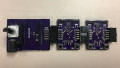
The Picaxe 08M2 microcontroller (left) and HIH6030 sensor on a carrier board (right).
Microcontroller
The “brain” for the project is a Picaxe 08M2 microcontroller programmed using the Picaxe BASIC language. The 8-pin device features 2048 bytes of program memory (up to 1800 program lines), 128 bytes of RAM, and six port pins (C.0 through C.4 are I/O, C.5 is input only).
For the project, the port pins are dedicated to the following functions (details follow):
- C.0 – Operates a piezoelectric buzzer to provide an alarm.
- C.1 – I2C, SCL.
- C.2 – I2C, SDA.
- C.3 – Reads fan tachometer signal.
- C.4 – Turns fan on/off using the MOSFET (Q1) switch.
- C.5 – Not used (tied to ground through R3).
Humidity and Temperature Sensor
The project uses a Honeywell HIH6030 to monitor temperature and relative humidity. The chip has a supply voltage range of 1.8V-5.5V and uses an I2C interface to communicate with a microcontroller. R4 and R5 are the recommended pullup resistors. Capacitors C4 and C5 also follow the values recommended by Honeywell.
The device comes in a surface mount package (SOIC-8) and, for the project, is soldered onto a carrier board making it usable as a DIP-8 package.

Power supply for the project
Power Supply
A regulated 12V power supply (model F1650) that previously served as a power supply for a laptop is used for the project. The unit is fused and is rated to provide 12V at up to 3.5A – plenty of power for this application. This model is still readily available (e.g., on eBay) and can be obtained on the used surplus market as well. Of course, not all model F1650 power supplies are necessarily equivalent and you should check the output details of whichever power supply that you use.
The 12V supply is used to operate the fan and also provide 5V power. To implement the 5V supply, I used the venerable 78L05 (U1) 5V regulator along with capacitors C1 and C2. The 5V supply powers the Picaxe controller (U2), the HIH6030 sensor (U3), and the piezoelectric buzzer (SG1).
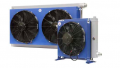
Fan
I used this fan from Thermaltake. The 200 × 200 × 30 mm fan’s specifications include 12V operation and ~130 CFM. D1 is a “flyback” diode used to suppress voltage spikes that occur across the inductive load presented by M1, the fan’s motor.
Fan Tachometer
The fan used has three connections on the cable: Vcc (+12V), ground, and tachometer out. On the unit I used, the wires were color coded as red, black, and yellow, respectively. The tachometer signal comes from a Hall effect sensor internal to the fan. Additionally, there are two magnets internal to the fan. Normally the tachometer signal is at 12V. When a magnet passes the Hall effect sensor, the signal switches to ground. It is configured as an open collector output with a pullup resistor to 12V internal to the fan.
We want the 08M2 input port C.3 to read the tachometer signal, but at 5V, not 12V. To accomplish this, we use R3 pulled up to 5V and diode D2 to prevent the 12V from reaching the 08M2 while preserving the pulses that correlate with the RPM of the fan. Note also that, because there are two magnets, there are two pulses per revolution.
Not all fans with a “third wire” tachometer signal work the same. I have seen ones where there was no internal pullup resistor and I have even seen ones where there was no internal connection at all! It's a good idea to test the functionality of the tachometer signal before using it in the project.

Piezoelectric buzzer (left) and IRL540 MOSFET (right)
Fan Control Switch
The fan is operated by a 08M2 output bit (C.4) connected to the gate of Q1, an IRL540 N-channel power MOSFET. Q1 is used in a "low side" driver configuration such that it will sink the fan’s current when the voltage of the gate, relative to its source pin, which is at ground, is increased by just a few volts.
The IRL540 is well-suited for the application because when the gate is near +5V (relative to the source), the device’s resistance is rated to be only 0.077Ω, and it is able to sink a much greater amount of current than the rated 0.23A of the fan. Thus, when the Picaxe output pin is set to a logic level “high” (~5V), the fan turns on and when the output pin is at a logic level “low” (<0.6V), the fan is off.
R1 is used to pull down the voltage at the gate of Q1 when the Picaxe output port is in a high impedance state, such as during power up.
Piezoelectric Buzzer
SG1 is a generic 5V buzzer. I measured the current drawn by the device at 5V as 24mA. Since that amount is near the Picaxe port's maximum output current, current-limiting resistor R6 is used. SG1 is connected to Picaxe output C.0 and functions as a notification/alarm buzzer. Even with R6, it is suitably loud.

The project circuit on a breadboard: 12V components (left) and 5V components (right).
Firmware
Before presenting the program code listing, some explanation of the basic tasks that the software must perform is in order.
Reading Humidity and Temperature Values
To thoroughly understand how to use the HIH6030 sensor, it is advisable to become familiar with a technical note from Honeywell detailing I2C communications with the sensor (PDF here).
The default I2C address of the sensor is 0x27, and Picaxe BASIC wants the 8-bit left-shifted value of 0x4E. When the device powers up, it will accept a data byte of 0xA0 to put it into “command mode”, if one is received within 10 milliseconds. Command mode can be used to set alarms, read EEPROM and even configure the default I2C address. There is a Honeywell technical note on command mode if you want to know more (PDF here). We are not, however, using command mode at all for the project and explicitly execute a software delay on power up to prevent the possibility of entering command mode.
We can read the sensor's temperature and relative humidity values by first sending the device a measurement request. To do this, we simply issue a write to the slave address. The sensor responds with an acknowledge (ACK), and the Master device then generates a “STOP” condition. For Picaxe BASIC, we have to send a data byte along with the initial write command to complete the transaction. Thus, we send a “dummy” data byte of 0xFF, which is always ignored by the sensor.
After issuing a measurement request and waiting a short time (~37 milliseconds) for the measurements to complete, we can read the sensor's values by retrieving four bytes of data as illustrated below.

Data stream read from the HIH6030 sensor (figure courtesy of Honeywell). Click to enlarge.
The data stream contains status, humidity, and temperature values. Status values can be 0b00 = normal, 0b01 = stale data, 0b10 = in command mode, and 0b11 = not defined. See the technical note for a full explanation of the status codes. In our project, the status value must be equal to 0b00 indicating a normal transaction. Any other received status value indicates a sensor or transmission error and will result in an alarm sounding in an infinite loop.
The Picaxe will read the four values and store the 14-bit humidity value (after masking the status bits) in one variable and the 14-bit temperature value (after dividing the value by 4 to shift the bits right two places) into another variable.
These raw humidity and temperature values will be compared to the high and low humidity and temperature values that the user has set in the program to decide whether to turn the fan on or off. While it is the raw values that the program uses, it is necessary to understand the relationship between the raw values and the RH percentage and degrees (C) that they represent.
That relationship for percent relative humidity is given by the formula below, where "Humcount" is the 14-bit raw humidity value.

For temperature, the relationship is given by the formula below, where "Temcount" is the 14-bit raw temperature value.

Configuring the Fan’s On and Off Thresholds
For both humidity and temperature, the program uses an “on” threshold and an “off” threshold. If the sensor value equals or exceeds the “on” value, the fan will turn on. If the fan is on and the value drops to the “off” value, the fan will turn off. By separating the threshold values, we prevent the fan from rapidly oscillating around one value. This is referred to as hysteresis.
To set the threshold values in the program, we convert RH percentage and degrees (C) to raw values that the program uses in the variables HumH (high humidity threshold), HumL (low humidity threshold), TemH (high temperature threshold), and TemL (low temperature threshold).
For humidity: raw value = RH(%)/0.0061.Thus, if you want to set the high RH threshold to 82% RH and the low threshold to 74% RH:
- 82/0.0061 = 13442.62, set HumH = 13443
- 74/0.0061 = 12131.15, set HumL = 12131
For temperature: raw value = (degrees (C) + 40)/0.01007. Thus, if you want to set the high temperature threshold to 29 degrees (C) and the low threshold to 27.5 degrees (C):
- (29+40)/0.01007 = 6852.04, set TemH=6852
- (27.5+40)/0.01007 = 6703.08, set TemL=6703
Fan Operating Modes
The operating mode of the fan is set in firmware by the user setting the symbol UMODE, which sets the value of the program variable, MODE, in the Picaxe code. Only values of 1, 2, or 3 are functional. The fan will not operate with other values.
- When MODE is set to 1, the fan will operate based on the sensor temperature value. When temperature, in sensor counts, equals or is greater than the value set in the variable "TemH", the fan will be switched on. When temperature, in sensor counts, equals or is lower than the value set in the variable "TemL", the fan will be switched off.
- When MODE is set to 2, the fan will operate based on the sensor RH value. When RH, in sensor counts, equals or is greater than the value set in the variable "HumH", the fan will be switched on. When RH, in sensor counts, equals or is lower than the value set in the variable "HumL", the fan will be switched off.
- When MODE is set to 3, sensor values for both temperature and humidity are used to control the fan. That is, when either temperature or humidity measures are at, or exceed, the upper limits (TemH or HumH), the fan turns on. The decision to turn the fan off in mode 3 is more complicated and is detailed below.
For Mode 3, if the fan has been turned on as a result of only temperature rising to the upper limit, then when temperature decreases to the lower limit, the fan turns off. Similarly, if the fan turns on as a result of only humidity reaching the upper limit, then when humidity decreases to the lower limit, the fan turns off. The procedures are just like those in modes 1 and 2, respectively.
When the temperature and humidity have both risen to or beyond their respective upper limits, however, we will turn the fan off only if both lower limits have been met. To accomplish this, we track the two measures independently. That is, we track the characteristic (temperature and humidity) that caused the fan to turn on using bits in the program variable FMODE.
For example, if temperature rises to the upper limit, FMODE bit 0 is set and the fan is turned on. If humidity subsequently rises to the upper limit, FMODE bit 1 is set (the fan is already on). Now, suppose that temperature, but not humidity, falls to the lower limit. In this case, we clear FMODE bit 0, but the fan remains on because FMODE bit 1 is still set. When humidity falls to the lower limit, we clear FMODE bit 1. Now, the fan is turned off because both bits 0 and 1 of FMODE are cleared.
Checking RPM of the Fan
The fan speed for the unit that I used is stated as 800 RPM in the specifications. I measured the fan RPM for my unit, using two different frequency counters, and the result was about 900 RPM. As mentioned in the fan documentation, “Specifications are subject to change without notice”. I believe that this is such a case.
To measure the RPM in the project code, I used the Picaxe BASIC “count” command. The command counts the number of low-to-high transitions on a Picaxe input port bit (the project schematic uses port bit C.3). For a 5-second period, the count was at 151 ± a few counts. That comes out to 30.2 pulses per second or 1812 pulses per minute (at 4MHz, the speed of the 08M2). The fan has two magnets that pass by the Hall effect sensor, so we need to divide the number of pulses by 2 to get RPM. Doing so gives a value of 906 RPM, which is acceptably close to my other measurements that indicated an RPM of ~900.
The program uses this feature to detect whether the fan is actually turning when it is switched on. That is, the program samples the fan RPM and compares the number to a programmed minimum value that is set in firmware using the variable mRPM. The default for mRPM is 100, but the value can be changed by the user. Thus, if RPM is less than mRPM after the fan is switched on, we assume a fan error.
We also use this feature to detect if the fan is turning when it is switched off. That is, if RPM is greater than mRPM after the fan is switched off, we assume a fan error.
The fan does not have a brake; when it is switched off, RPM values will decline over a few seconds before reaching a value of 0. Additionally, when first switched on, a small amount of time is required before RPM reaches the normal peak value. We have a 5-second delay in software before we measure RPM for an additional 5 seconds. Thus, we can overlook start-up and shut-down RPM values, while checking temperature and humidity every 10 seconds.
Code
The code for the project is given below, and the file can be downloaded at the end of the article.
001	; AxeFan.bas-PICAXE code to accompany the article -
002	; "Build a temperature and/or humidity controlled fan"
003	;
004	; *** This software is offered stricly as-is with no warranties
005	; whatsoever. Use it at your own risk. ***
006	init:
007	;--------------------------------
008	; User sets the following turn on and turn off values for temperature
009	; and humidity as 16 bit sensor counts in decimal
010		SYMBOL TemH=6852  ;29 degrees (C)
011		SYMBOL TemL=6703  ;27.5 degrees (C)
012		SYMBOL HumH=13443 ;82 % RH
013		SYMBOL HumL=12131 ;74 % RH
014		SYMBOL mRPM=100	;151=~900 RPM full on
015	; User sets the mode to 1=temperature only, 2=humidity only, 3=both
016		SYMBOL UMode=3
017	;--------------------------------
018	; The SYMBOLS below are for program variable use
019		SYMBOL HUM=W0	; 16 bit humidity
020		SYMBOL TEMP=W1	; 16 bit temperature
021		SYMBOL status=B4	; HIH status (must be 0)
022		SYMBOL Fstatus=B5	; fan bit status (0=off, 1=on)
023		SYMBOL MODE=B6	; fan mode
024		SYMBOL FMODE=B7	; to track which (T or H) or both turned the Fan on
025					; FMODE bit 0=T and bit 1=H
026		SYMBOL RPM=W4	; to measure Fan RPM
027	; Note: Fan=4=MOSFET G on C.4
028		SYMBOL Fan=4;
029	; Note: Buzzer=0=piezo on C.0
030		SYMBOL Buzzer=0;
031	; Note: RPMin=3=Fan tach on C.3
032		SYMBOL RPMin=3
033	;--------------------------------
034		let MODE=UMode
035		; get fan bit status, Fstatus=1 if fan GPIO is on
036		Fstatus=pinc.4
037		gosub FanOff  	; should boot up off but switch it to be sure
038		let Fstatus=0
039	; I2C address is $27 shifted=$4e
040		hi2csetup I2CMASTER, $4E, i2cslow, i2cbyte
041		let B5=$ff		; dummy arg
042		pause 30		; wait past command window
043		gosub PU_tone
044	;--------------------------------
045	; main loop
046	main:	;get temperature and humidity
047		hi2cout (B5)	; wake up kick to start measurement cycle
048		pause 60		; wait for measurement cycle (nominally 36.65 ms)
049		hi2cin (B1)		; Hum hi
050		hi2cin (B0)		; Hum low
051		hi2cin (B3)		; Tem hi
052		hi2cin (B2)		; Tem lo
053		let status=B1 & 000000   ; get status bits
054		let B1=B1 & 111111	; mask status
055		let W1=W1/4			; shift temperature
056	; if status is not 0, we have a read error indicating either a
057	; transmission error or a sensor error.
058	; ** This results in an error trap. **
059		if status<>0 then
060			goto TerrorS
061		endif
062	; handle fan on/off depending on the operating mode
063	MODE1:
064	; mode 1 is temperature only
065		if MODE = 1 then
066			if TEMP >=TemH then
067				gosub FanOn
068		      endif
069			if TEMP <=TemL then
070				gosub FanOff
071			endif
072		endif
073	MODE2:
074	; mode 2 is humidity only
075		if MODE=2 then
076			if HUM >=HumH then
077	              gosub FanOn
078			endif
079			if HUM<=HumL then
080			  gosub FanOff
081			endif
082		endif
083	MODE3:
084	; mode 3 is both humidity and temperature
085		if MODE=3 then
086			; If fan is off, should we turn it on?
087			if Fstatus=0 then
088				if TEMP >=TemH then
089					FMODE=FMODE|1	;set b0
090					gosub FanON
091				endif
092				if HUM >=Humh then
093					FMODE=FMODE|2	;set b1
094					gosub FanOn
095				endif
096			elseif Fstatus=1 then
097			;else
098			; if fan is on should we turn it off?
099				if TEMP <=TemL then
100					FMODE=FMODE&2	;reset b0
101				endif
102				if HUM <=HumL then
103					FMODE=FMODE&1	;reset b1
104				endif
105				if FMODE=0 then
106					gosub FanOff
107				endif
108			endif
109		endif
110
111	next1:
112	; get fan bit status, Fstatus=1 if fan GPIO is on
113		Fstatus=pinc.4
114	; delay for 10 seconds before looping
115		pause 5000;
116	; check fan RPM as part of the 10 sec delay
117		count RPMin,5000,RPM
118		if Fstatus=1 then
119			if RPM < mRPM then
120				goto TerrorF ; fan error - RPM too low!
121			endif
122		elseif Fstatus=0 then
123		;else
124			if RPM >= mRPM then
125				goto TerrorF  ; fan error - RPM too high!
126			endif
127		endif
128		goto main
129	;--------------------------------
130	; Error Traps (infinite loops)
131	; sensor or transmission error - give continuous fast beeps
132	TerrorS:
133		switchon Buzzer
134		pause 35
135		switchoff Buzzer
136		pause 100
137		goto TerrorS
138	; Fan RPM eror - give continuous slow beeps
139	TerrorF:
140		switchon Buzzer
141		pause 75
142		switchoff Buzzer
143		pause 300
144		goto TerrorF
145	;--------------------------------
146	; subroutines
147	FanOn:
148		if pinc.4=0 then switchon Fan endif
149		return
150	FanOff:
151		if pinc.4=1 then switchoff Fan endif
152		return
153	PU_tone:
154	; power up - three beeps
155		switchon Buzzer
156		pause 100
157		switchoff Buzzer
158		pause 100
159		switchon Buzzer
160		pause 100
161		switchoff Buzzer
162		pause 100
163		switchon Buzzer
164		pause 100
165		switchoff Buzzer
166		return
Program Structure Comments
Lines 8-16: User-defined values for symbols to set program variables that control the fan.
- TemH, TemL, HumH, HumL are the high and low raw-data values for controlling the fan on/off set points.
- mRPM is the RPM value used to determine if the fan is turning when on and not turning when off.
- UMODE sets the operation mode for the fan (1 = temperature only, 2 = humidity only, 3 = both).
Lines 17-32: Symbol definitions for program variables.
Lines 33-43: Initialization.
- Initialization of the I2C interface.
- Issue starting tone (three beeps).
Lines 44-128: Main loop.
- Lines 47-61: Read HIH3060 sensor; evaluate status bits and store humidity and temperature raw-data values.
- Lines 62-111: Decide on whether to turn the fan on or off for the current operating mode.
- Lines 116-127: Check for acceptable fan RPM depending upon on/off status.
Lines 129-144: Error alarm traps (infinite loops).
- Lines 132-137: Error alarm (fast beeps) if status byte does not equal 0 (transmission or sensor error).
- Lines 139-144: Error alarm (slow beeps) if RPM is below mRPM when fan is on or above RPM when fan is off.
Lines 145-166: Utility subroutines.
Closing Thoughts
This project presents an economical and relatively simple example of automating the control of a fan. The implementation can be accomplished with just a few ICs, primarily because the sensor and the microcontroller are highly integrated devices. The system is flexible in that it can be configured to be controlled by temperature or humidity or the combination of both temperature and humidity. Additionally, the user can easily configure the characteristics of the control parameters, changing them to suit a variety of applications.
The source code for the project can be downloaded by clicking the link below:
Give this project a try for yourself! Get the BOM.