 Facebook
 Google
 GitHub
 Linkedin
Create an Object Tracking System Part 2: Controlling a Servo
This project explains the basic operation of servo motors and how to interface with them using an Arduino Uno.
Learn the basic operation of servo motors and how to interface with them using an Arduino Uno.
The second part of this project series looks at servos and will implement code to move a servo to random positions every second in preparation for integrating with the ultrasonic sensors from the next phase of this project series.
Part 1 of this project can be found here: Create an Object Tracking System: Using Built-in Arduino Libraries
Required Parts:
- Arduino Uno
- 5V tolerant 180° servo
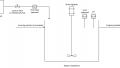
The wiring diagram is below and is fairly simple: just 3 connections. In the diagram, red is 5V, black is GND, and yellow is the control wire.

Figure 1: Arduino/Servo Wiring Diagram
A servo is controlled by sending a PWM (Pulse Width Modulation) signal to the control pin. The pulse width of the PWM signal will command the position of the servo. Below is an example of a servo's pulse width control scheme. As you can see, at a minimum pulse width (0.5ms) the servo is at the leftmost extreme of its articulation and with a maximum pulse width (2.5ms) the servo is at the rightmost extreme of its articulation.
![]()
Figure 2: Servo Control Scheme
The Arduino IDE comes with a library (Servo.h) for interfacing with servos. Implementing this library will greatly simplify the code needed to drive Servo. The library handles establishing PWM frequencies and gives a simple command for controlling position: ServoName.write(X) where "ServoName" is a user selected, unique name for that output, "(X)" is the desired position in degrees, and ".write" is the required syntax. The code snippet below is an example that will generate a random position every second and move the servo to that position. During the integration phase, the random number generation will be replaced with an output from the tracking algorithm.
It is recommended that if you are only powering your Arduino from the USB port, you should plug in the DC supply before powering the servo. The current draw from the servo can cause the 5V rail to droop and may cause the board to reset and become unstable.
#include "Servo.h"               // Implements easy to use servo controls

Servo ServoOne;                  // Generates an instance of a servo object
int ServoPosition = 0;           // Variable to be used to assign position of servo

void setup()                     // Initialize
{
  ServoOne.attach(9);            // Assigns pin 9 as a servo
}

void loop()                      // Main loop
{
  ServoPosition = random(0,180); // Generates a random number and stores it in ServoPosition
  ServoOne.write(ServoPosition); // Commands servo to spin to position
  delay(1000);                   // Delays for 1000 ms
}
This project leverages a native library to simplify interfacing with a peripheral. In the next project we will write our own functions to create the object tracking algorithm.
Next Article in Series: Integrating Servo Control with Object Detect
Give this project a try for yourself! Get the BOM.


is part 3 coming any time soon?
What a BS article. Where is the good stuff? none of these info is new or even complete.