
 Facebook
 Google
 GitHub
 Linkedin
The BBC Micro:bit Adjustable Brightness Alarm: A Radio Shack Remix
In this project article, we’ll create a programmable device that alerts users to changes in ambient light levels. Along the way, we’ll learn about astable multivibrators and the Darlington pair.
This Radio Shack Classics Circuit Remix combines a BBC micro:bit and a vintage Science Fair Sensor Robot 20 kit into a device that can monitor light levels and trigger an audible alarm when the brightness exceeds a preset threshold. By integrating these components, we aim to illustrate both the versatility of the micro:bit and the enduring educational value of the classic hobbyist kit.
As with previous entries in the series, this project is based on one from the manual of the vintage kit—we’re simply updating it to include modern microcontroller functionality by using a micro:bit board as a light sensor and to adjust the light-detection threshold.
This offers several advantages over the original analog setup. For one thing, the use of digital processing allows more sophisticated control over the sensor. Instead of manually turning a dial, we can set and adjust the light-sensing threshold within the code. The micro:bit can also process the light data to apply filters or averages, ensuring that transient changes in light levels don’t falsely trigger the alarm.
Furthermore, the micro:bit allows light-level data to be logged and stored as numerical information or displayed visually on a monitor. Adding another layer of functionality, the micro:bit’s LEDs serve as visual indicators as well as light sensors.
Figure 1 shows the completed project, which we’ll call the Remixed Brightness Alarm.
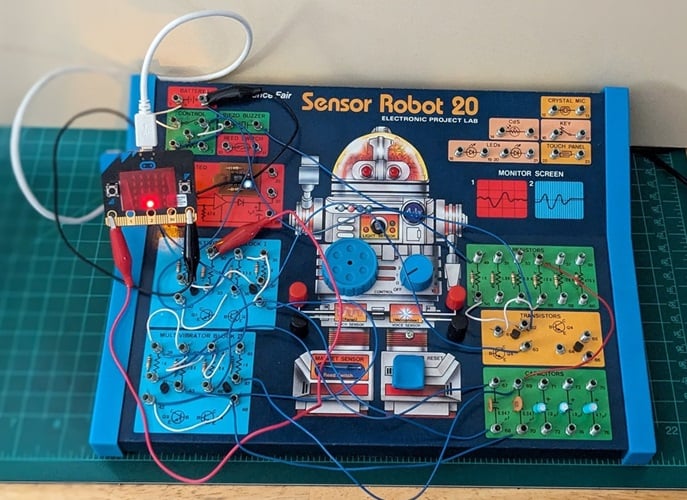
Figure 1. The complete Remixed Brightness Alarm. Image used courtesy of Don Wilcher
Note: Radio Shack sold two different versions of the project kit pictured here. The version we’re using was introduced in 1988, but a slightly different Sensor Robot 20 kit was available in Radio Shack’s 1985 catalog. We are also using a Version 2 micro:bit.
The Classic Brightness Alarm Project
Figure 2 shows the original Brightness Alarm project instructions as they appeared in the Sensor Robot lab manual.
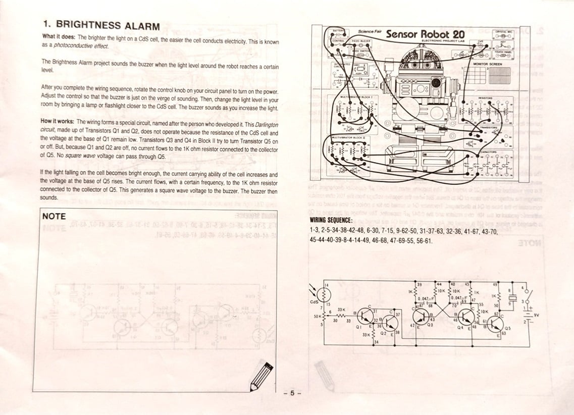
Figure 2. [Click to enlarge] The Brightness Alarm project instructions from the original Sensor Robot 20 manual. Image used courtesy of Don Wilcher
Figure 3 provides a close-up view of the circuit schematic.
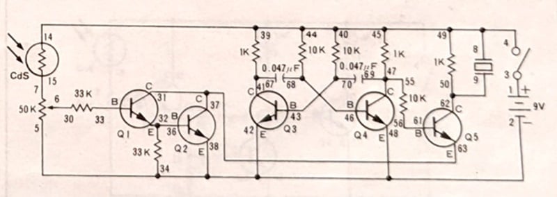
Figure 3. The Brightness Alarm schematic from the original manual. Image used courtesy of Don Wilcher
This version of the Brightness Alarm includes five electronic subcircuits:
- The cadmium-sulfide light sensor (I4).
- The 50 kΩ potentiometer.
- The Darlington circuit (Q1 and Q2).
- The astable multivibrator (Q3, Q4, and RC loads).
- The transistor-driven piezo buzzer circuit (Q5 and the piezo crystal).
The classic project uses a cadmium-sulfide (CdS) photoresistor to detect light. CdS photocells change their resistance based on the intensity of light falling on them. The sensitivity of the light detector is controlled by manually adjusting the potentiometer.
The Darlington circuit, astable multivibrator, and piezo buzzer circuit are present in both the classic and remixed versions of the project. We’ll discuss their operation later on in the article. However, the remix of the Brightness Alarm replaces the CdS cell and the 50 kΩ potentiometer with a micro:bit microprocessor board. This feature upgrades the classic Brightness Alarm to a programmable light sensor capable of logging light level data and digitally adjusting the detection threshold.
The Remixed Brightness Alarm: Design and Operation
Figure 4 illustrates how the various parts of the Remixed Brightness Alarm work together. Except for the BBC micro:bit, all of the parts shown are included in the Sensor Robot kit.
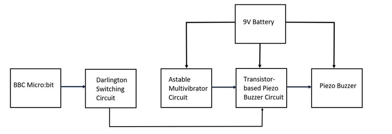
Figure 4. The Remixed Brightness Alarm block diagram. Image used courtesy of Don Wilcher
The micro:bit acts both as a light sensor and as the brain of the device. When it detects ambient light levels in excess of the programmed threshold, it biases the Darlington circuit. The Darlington circuit activates the transistor-based piezo buzzer, which sounds an alarm tone. The frequency of this tone is determined by the astable multivibrator.
As we already mentioned, the light-detection threshold is set in the micro:bit’s code and can be adjusted based on the project requirements. We’ll discuss the programming process later in this article, once we’ve finished putting together the physical circuit. Before any of that, however, let’s examine the operation of the Brightness Alarm’s various subcircuits.
The Micro:bit Microprocessor Board
Figure 5 shows the layout of a Version 2 BBC micro:bit.
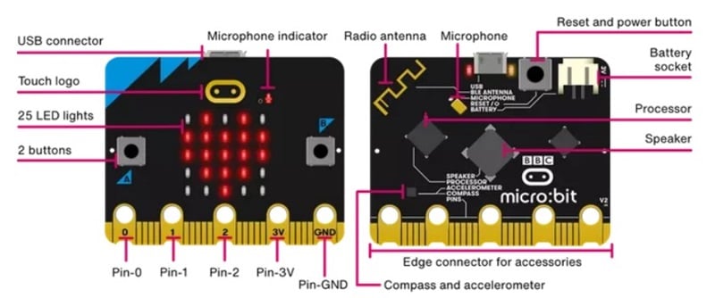
Figure 5. Layout of the BBC micro:bit (Version 2). Image used courtesy of microbit.org
LEDs can act both as light emitters and light detectors. When light hits the P-N junction of an LED, it generates a small current due to the photoelectric effect. This property is what allows the micro:bit to use its 5x5 LED matrix as a light sensor.
To measure light, the micro:bit briefly reverse-biases the LEDs, causing them to act as capacitors. The micro:bit then measures the time it takes for the LEDs to discharge. We can tell how much light is hitting the LEDs by how long this takes—the brighter the light, the faster the discharge occurs. The discharge time is then converted into a digital value ranging from 0 to 255, which represents the detected light level.
In the completed device, the P0 pin of the micro:bit is connected to the first of the Darlington circuit’s two NPN transistors. When the detected light level is greater than the programmed threshold value, it triggers the following sequence of events:
- The micro:bit outputs a 3 V logic-high signal to its P0 pin, which is connected to the first NPN transistor of the Darlington circuit (Q1).
- The P0 pin sends a small current to Q1’s base, causing Q1 to turn ON.
- Because Q1 is ON, the second transistor in the Darlington circuit (Q2) turns ON as well. This completes the circuit for the piezo buzzer.
- The now-operational piezo buzzer emits an audible alarm tone.
When the light level is below the programmed threshold, the P0 pin remains logic-low, the Darlington circuit stays OFF, and the buzzer is silent.
The Darlington Circuit
The Darlington circuit, also known as the Darlington pair, consists of two NPN transistors (Q1 and Q2) connected in series. When a small current flows into the base of the first transistor, it triggers the second transistor. Each transistor amplifies the signal further, resulting in a significantly boosted current gain.
Figure 6 shows a typical Darlington pair.
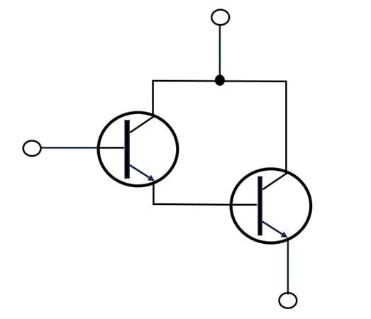
Figure 6. The basic Darlington configuration. Image used courtesy of Don Wilcher
In the Remixed Brightness Alarm, the Darlington circuit is necessary because the piezo buzzer requires more current than the micro:bit can supply directly. The first transistor in the Darlington pair amplifies the small signal from the micro:bit, while the second transistor provides the current to the buzzer. The amplification process ensures that even a minimal input signal is sufficient to drive the buzzer.
This design also reduces the power consumption of the micro:bit, which is convenient if you choose to power the microprocessor board using a battery. The micro:bit can be powered using either a 3 V battery pack or a standard USB cable plugged into your personal computer.
The Astable Multivibrator and Piezo Buzzer Circuit
At the core of the Brightness Alarm circuit is an astable multivibrator built from two NPN transistors (Q3 and Q4). An astable multivibrator continuously oscillates between two states regardless of the external input, producing a consistent square wave signal. The frequency of the oscillation is determined by the values of the Brightness Alarm’s capacitors (C1 and C2) and resistors (R1, R2, R3, and R4).
The output of the astable multivibrator is connected to the base of another NPN transistor (Q5). This transistor acts as a switch to control the piezo buzzer. When the astable multivibrator produces a logic-high output, Q5 conducts, allowing current to flow through the piezo buzzer and produce sound. This rapid switching creates the alarm tone we hear when the brightness level exceeds the set threshold.
The piezo buzzer itself is a transducer that converts the electrical pulses from the multivibrator into mechanical vibrations, which in turn produce sound waves.
To determine the output frequency of the astable multivibrator circuit, we use the following equation:
$$f~=~ \frac{1.44}{(R_1~+~2R_2)C}$$
where:
f = the frequency of the alarm tone
R1 = the value of the resistor R1, which is also the value of R4
R2 = the value of the resistor R2, which is also the value of R3
C = the value of the capacitor C1, which is also the value of C2
For the Brightness Alarm circuit, we’ll use the following resistance and capacitance values:
R1 = 1 kΩ
R2 = 10 kΩ
C = 0.047 μF
If we plug these values into the above equation, we get:
$$f~=~ \frac{1.44}{[1~\text{k} \Omega~+~2(10~\text{k} \Omega)]0.047~\mu \text{F}}~=~1.46~\text{kHz}$$
As the above equation demonstrates, you can adjust the frequency of the alarm tone by selecting different resistors and capacitors.
Assembling the Project Hardware
We're now ready to put everything together. Figure 7 shows the the complete schematic for the Remixed Brightness Alarm.
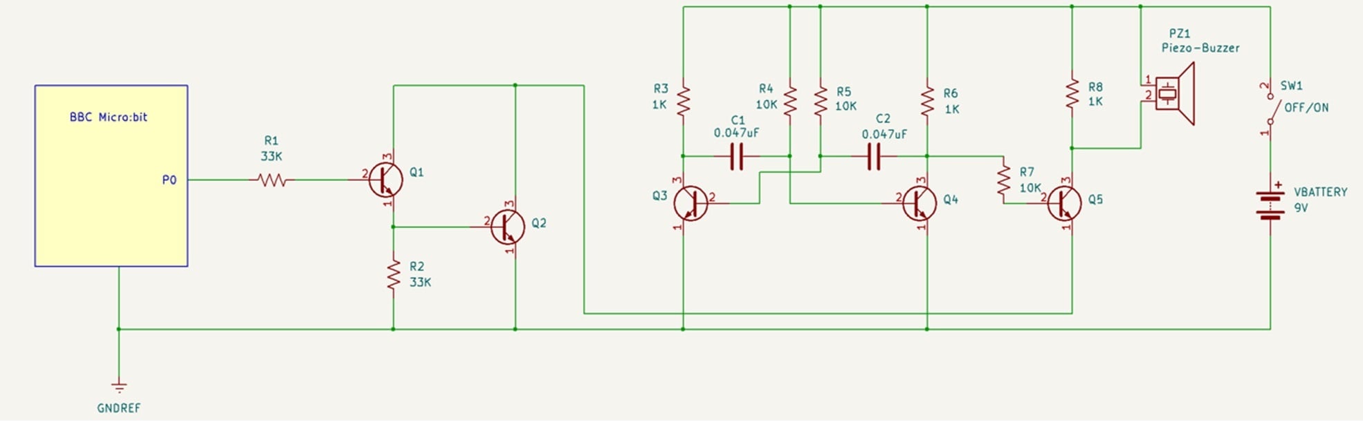
Figure 7. [Click to enlarge] The Remixed Brightness Alarm schematic. Image used courtesy of Don Wilcher
Most of the wiring instructions are the same as they would be in the classic version of the project. You can find these instructions in Figure 2. However, we still need to connect the micro:bit to the rest of the device. This is done using two test leads with alligator clips.
Figure 8 illustrates the two wiring connections between the micro:bit and the Sensor Robot kit. I’ve color-coded the two test leads for ease of reference.
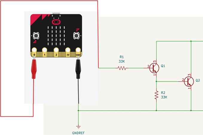
Figure 8. The micro:bit is connected to the Sensor Robot kit via two test leads, one attached to P0 and the other to GND. Image used courtesy of Don Wilcher
The procedure is as follows:
- Connect one end of the red test lead to pad P0 of the micro:bit and the other end to spring terminal 30 of the Sensor Robot kit. Spring terminal 30 connects to the 33 kΩ series resistor that biases the Darlington pair.
- Connect one end of the black test lead to the micro:bit’s GND pad and the other end to spring terminal 3 of the kit. Spring terminal 3 is the negative/ground side of the Sensor Robot kit’s 9 V battery.
Programming the Micro:bit
Now that we’ve assembled the hardware, we need to program a light detection threshold into the micro:bit. I did this in MicroPython; my code is shown below.
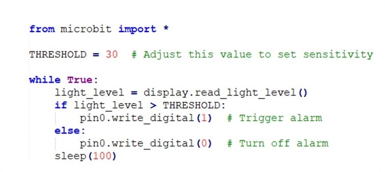
In the code above, the THRESHOLD variable sets the light level threshold. You can adjust the threshold value as needed to account for different environmental lighting conditions.
The MicroPython code continuously reads the light level from the micro:bit’s LED matrix and compares it to the threshold value. If the detected light level exceeds the threshold, the P0 pin is set logic-high, activating the Darlington circuit and triggering the piezo buzzer. If the light level is below the threshold, the P0 pin is set logic-low, silencing the buzzer.
You can easily load the MicroPython code into the micro:bit using a programming platform like Mu. The final hex code can be flash programmed to the micro:bit.
Programming Alternatives
MicroPython isn’t your only option. You can also easily develop light detection code in the Microsoft MakeCode micro:bit programming environment (Figure 9). It’s possible to view the equivalent JavaScript and Python code within this online programming environment.

Figure 9. A Microsoft MakeCode simulation session with the micro:bit displaying light levels and port P0 output control. Image used courtesy of Don Wilcher
Alternatively, you can program the micro:bit using Blockly code blocks. This approach is helpful if you want to add or change graphics, and for simulating the micro:bit’s light sensing and control features. In the built-in simulator, the user can experiment with various threshold values and immediately see responses displayed on the micro:bit’s 5x5 LED matrix.
Testing the Completed Project
Once the light detection code has been programmed into the micro:bit, our project is complete! To test the Brightness Alarm, turn it on by rotating the blue control knob on the Sensor Robot kit. Next, point an appropriate light source (a flashlight, for example) at the micro:bit’s LEDs. You should hear an alarm tone from the piezo buzzer.
Click on the video in Figure 10 to watch me go through the testing process.
Figure 10. The Remixed Brightness Alarm in action. Video used courtesy of Don Wilcher
Try moving the flashlight closer or farther from the LED matrix to examine the Brightness Alarm’s response to different light levels. You can also experiment with various light sources and observe the Brightness Alarm’s response. Have fun!










Nice. Btw, I have here some rádio shack kits 😊