Facebook
 Google
 GitHub
 Linkedin
An Introduction to Oscilloscope Probes
This article looks at various types of oscilloscope probes and how to use them.
This article looks at various types of oscilloscope probes and how to use them.
Let's Talk Oscilloscope Probes...in General Terms
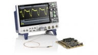
An oscilloscope (aka scope or o-scope) is a very powerful tool—and arguably the most used piece of equipment—for electrical engineers or anyone else wishing to measure electrical characteristics of electronic devices. However, you need more than just an oscilloscope; you also need at least one probe.
When selecting a probe for your o-scope, it's best to check the o-scope's manual to see what kind of probe it recommends. If your manual is nowhere to be found (which is often the case in the real world), then go to your oscilloscope manufacturer's website for recommendations.
The following information should also be considered when choosing probes:
- Ensure the probe's input connector matches the connector on your scope.
- Most oscilloscopes have BNC-type connectors; SMA is another possibility. See Figures 1 and 2 below.
- Choose a probe whose input resistance and capacitance match the input resistance and capacitance of your scope. Typically, it is desired for the probe to have the least influence on the circuit that is being measured—this is referred to as the loading effect. Resistance and capacitance matching is critical for guaranteeing proper signal transfer and signal accuracy.

Figure 1. BNC connector. Image courtesy of Swift.Hg [CC BY-SA 3.0].

Figure 2. SMA connector. Image courtesy of Swift.Hg [CC BY-SA 3.0].
Most modern scopes allow you to choose either 50 Ω or 1 MΩ input resistance. For general-purpose testing, a 1 MΩ input is commonly used. A 50 Ω input resistance is used for high-speed signals (think microwaves), propagation delays in logic circuits, and circuit-board impedance testing.
Unlike a scope's standard input resistance of either 1 MΩ or 50 Ω, a scope's input capacitance can vary depending on the scope's bandwidth and other design features. With that said, a common input capacitance for many 1 MΩ scopes is 20pF. However, this value can range from 5pF up to 100pF. The best approach, for matching a probe with a scope, is to first choose a probe whose capacitance is within the range of your scope and then fine-tune the probe's capacitance by adjusting its compensation network using the probe's trimmer capacitor, if possible. This process is known as compensating your probe.
How Many Probes, and What Types Do You Need
How many probes, and the type of probes, you may need depends on the situation at hand. For example, if only individual DC voltage measurements are needed, then a passive 1 MΩ single-ended voltage probe would be required. However, if you're measuring the setup-and-hold times of a high-speed signal—such as the NAND data lines on a solid state drive (SSD)—then you'll want to use two active high-speed differential probes. See Figure 4 for an example of this type of measurement.

Figure 3. A Tektronix active differential probe. Image from this datasheet (PDF). Note the 10× and 1× attenuation selector switch.

Figure 4. High-speed setup-and-hold time voltage measurements.
Passive Probes
Passive probes are the most commonly used probes for taking general-purpose measurements. Passive probes are constructed using wires, connectors, a housing, and, if required, compensation or attenuation resistors or capacitors. No active components—such as transistors or amplifiers—are used within these types of probes. Generally speaking, passive probes are easy to use, relatively inexpensive, and fairly rugged.
Passive probes are typically available in the following configurations:
- 1×: no attenuation
- 10×: factor-of-10 attenuation
- 100×: factor-of-100 attenuation
- 1000×: factor-of-1000 attenuation
Attenuation probes serve to multiply the voltage measurement range of the oscilloscope by using an internal resistor that, when used in conjunction with the input resistance of the scope, creates a voltage divider. As an example, a typical 10× probe houses an internal 9 MΩ resistor that, when used with a 1 MΩ scope, creates a 10:1 attenuation ratio at the scope's input channel. This means that the displayed signal on the scope will be 1/10th the magnitude of the actual measured signal. This attenuation feature is useful for the following reasons:
- It allows for the measurement of a signal that might exceed the limits of the oscilloscope.
- The attenuation circuitry results in higher resistance (generally a good thing) and lower capacitance, which is important for high-frequency measurements.
See Figure 5 below for a typical schematic of a 10× passive probe.
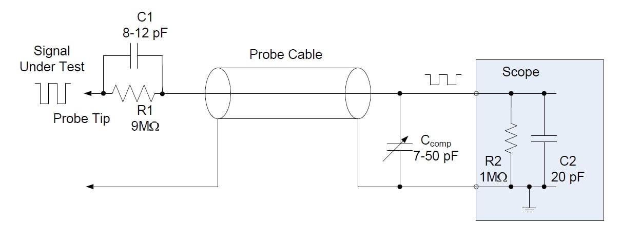
Figure 5. Typical schematic of a 10× passive probe.
Active Probes
Active probes get their names because they contain active components, such as FETs or amplifiers (see Figure 6 below). Active probes are commonly used for taking high-speed measurements (>500 MHz) or on high-impedance circuits. For applications such as these, passive probes are not adequate: they can cause severe circuit loading (because the input impedance is not significantly higher than the circuit’s output impedance) and degradation of high-frequency characteristics (because the probe has too much capacitance).
Active probes employ internal FETs, or other active components, that present extremely high input resistance and low input capacitance (~1 pF). Active probes are externally powered, which allows them to amplify signals without using power from the circuit under test.
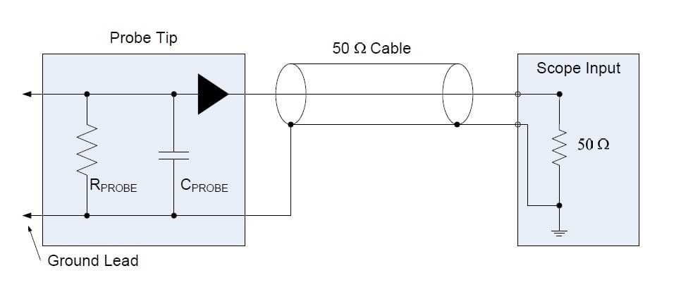
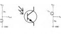
Figure 6. Typical schematic of a single-ended active probe.
Active probes have a bandwidth from 500 MHz to 4 GHz, and they usually have a 50 Ω output impedance (which matches the 50 Ω input impedance of the scope). However, active probes with 1 MΩ output impedance also exist (see Figure 7 below).

Figure 7. Active probe (1 MΩ output impedance). Image courtesy of Teledynelecroy.com.
One limitation of active probes, as seen in Figure 7 above, is their limited voltage range. Typically this range is from ±0.6 to ±10V, with maximum voltage ratings of ±40V.
Differential Probes
Differential probes measure differential signals. That is, they measure the difference between any two points. This is in contrast to a single-ended probe, which measures the difference between a single point and ground. Differential probes are especially popular for measuring high-frequency signals or signals of very low amplitude (i.e., approaching the noise floor). Differential probes use a differential amplifier to convert the difference between two signals into a voltage that can be sent to a typical single-ended scope input. See Figure 8 below.
Differential probes offer high common-mode rejection performance over a broad frequency range.
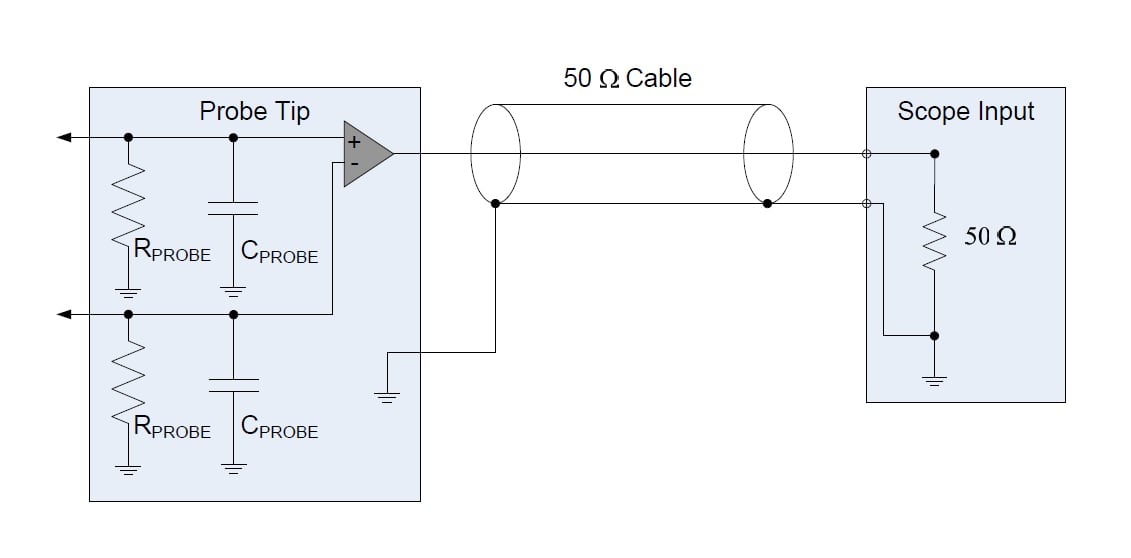
Figure 8. Typical schematic of an active differential probe.
Current Probes
A current probe provides a noninvasive method for measuring the electrical current flowing through a conductor. A DC current probe employs a Hall-effect sensor for measuring the magnetic field generated by a DC current as it passes through the probe’s ferrite core. An AC current probe uses a current transformer for measuring AC current as it flows through the probe’s core. Current probes that measure both AC and DC currents are also available, and rather common.
The ferrite cores within current probes are essentially cut in half, such that the core can be “opened up,” allowing for the conductor under test to be placed inside the core; the core must be closed before taking current readings.
Figure 9 below shows the internal construction of a current probe, and Figure 10 shows the AC and DC current measuring devices.

Figure 9. A Fluke current measuring probe. Image courtesy of Fluke.

Figure 10. Left: AC-only current transformer. Right: Hall-effect sensor placed in the air gap for measuring DC-only current. Image courtesy of Fluke.
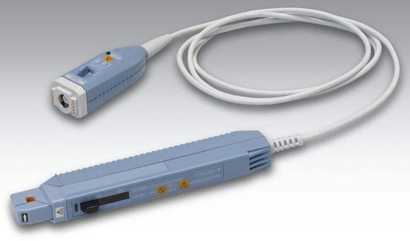
Figure 11. An example of a current probe. Image courtesy of yokogawa.com.
Probe Suggestions
In closing, I'd like to offer the following probe suggestions:
Always compensate your probes:
- There are slight input variations from scope to scope and even between different channels on the same scope. To overcome these variations, it's always good engineering practice to compensate the probe for the particular scope channel that you will be using.
Use appropriate probe tip adapters:
- Always use an appropriate probe tip and/or probe tip adapter whenever possible. See Figure 3 above for different types of adapters.
Keep ground leads short:
- Unnecessarily long probe ground leads may introduce significant inductance resulting in ringing and/or signal distortion.
- Keeping probe ground wires short is especially important when measuring high-speed signals and low-amplitude signals. Long grounding leads behave as antennas and can pick up noise, resulting in signal misrepresentation.
Supporting Information
- Basic Waveform Analysis with an Oscilloscope
- Rohde and Schwarz - HMO3042 Oscilloscope
- Webinar Replay: 12 Things to Consider when Choosing an Oscilloscope
Related Content