Facebook
 Google
 GitHub
 Linkedin
The Four EV Charging Modes in the IEC 61851 Standard
In this article, we’ll look at different EV charging modes specified by the International Electrotechnical Commission (IEC).
International standards are being developed to answer the needs of the EV market. Global EV uptake depends on well-established international standards that can address the safety, reliability, and interoperability issues of the EV market.
In this article, we’ll look at different EV charging modes specified by the International Electrotechnical Commission (IEC). These modes are specified in the IEC 61851 standard that deals with electric vehicle conductive charging systems. The standard describes four different charging modes called mode 1, 2, 3, and 4.
The IEC has developed other standards that deal with other aspects of the EV charging technologies. For example, the IEC 62196 discusses plugs, socket-outlets, vehicle connectors, and vehicle inlets while the IEC 61980 deals with electric vehicle wireless power transfer (WPT) systems.
Different Types of Cable Connections
The IEC 61851-1 describes three different types of connections as shown in the following figure:

The three main types of EV charging cables. Image used courtesy of the University of Zagreb
With Case A, the cable is permanently connected to the EV but it is detachable at the charging station (also called EVSE—electric vehicle supply equipment) EVSE side. Case B specifies a cable that is detachable at both ends and Case C is a cable that is permanently connected to the EVSE.
EV Charging Mode 1
With this mode, the EV is directly connected to a household socket. The maximum current of this mode is 16 A and its voltage should not exceed 250 V with a single-phase system and 480 V in the case of a three-phase network.

The basic structure of an EV hooking up to a household socket. Image used courtesy of the University of Zagreb
Mode 1 is the simplest possible charging mode and does not support any communication between the EV and the charge point. This charging mode is prohibited or restricted in many countries.
EV Charging Mode 2
Household socket-outlets do not always provide electric power according to the actual standards. Besides, socket-outlets and plugs designed for household applications might not be able to tolerate continuous current draw at the maximum rated value.
That’s why connecting an EV to the socket-outlet for a long time with no control and safety functions can increase the risk of electric shock. To solve this problem, specialists developed charging mode 2 that uses a special type of charging cable equipped with an in-cable control and protection device (IC-CPD).
The IC-CPD performs the required control and safety functions. The maximum current of this mode is 32 A and its maximum voltage should not exceed 250 V single-phase or 480 V three-phase. Mode 2 can be used with both household and industrial sockets.
The safety functions of this mode can detect and monitor the protective earth connection. Over-current and over-temperature protection are two other safety functions that mode 2 supports. Moreover, the EVSE can perform functional switching as it detects connection to the EV and analyzes its charging power demand.
Charging mode 2 and the associated cable are shown in the following figure.

Charging mode 2 and associated cable. Image (modified) used courtesy of University of Zagreb and Ali Bahrami
While mode 2 can be used for private charging, its public use is subject to restrictions in many countries.
EV Charging Mode 3
This mode utilizes a dedicated EVSE along with the EV on-board charger. The AC current from the charging station is applied to the on-board circuitry to charge the battery. Several control and protection functions are employed to guarantee public safety. These include verifying the protective earth connection and the connection between the EVSE and the EV.
Moreover, this mode can adjust the charging current to the maximum current capability of the cable assembly. The maximum current of this charging mode is 250 A with either a 250 V 1-phase or 480 V 3-phase network. It also supports an operational mode compatible with mode 2 where the maximum current is limited to less than 32 A for both 1-phase and 3-phase cases.
Any of the three possible connections (Case A, Case B, and Case C) can be used in this mode. Case B and Case C are shown below.

Case B and Case C in charging mode 3. Image used courtesy of the University of Zagreb
Let’s see how this mode defines the communications between the charging station and the EV. The control pilot circuit of mode 3 is shown in the following figure.

Control pilot circuit of mode 3. Image (modified) used courtesy of Energies.
Depending on the status of the switches S1, S2, and S3, different voltage levels will appear at the “pilot contact.” This can be used as a representation of different charging stages. The EV can begin a charging cycle as follows:
Before plugging in the charging cable, the switches S2 and S3 are off and S1 is connected to the 12 V DC supply. In this case, the voltage that the EVSE measures at the pilot contact is 12 V DC (the EVSE realizes that the EV is not connected yet).
After the charging cable is connected to both the EV and the EVSE, the controller on the EV side can turn on S3 to reduce the voltage of the pilot contact to about 9 V. This informs the EVSE that the cable is connected to both the EV and the EVSE. Moreover, the DC 9 V signal at the pilot contact tells the EV that the EVSE is not ready yet.
When the EVSE is ready to charge the EV, it connects S1 to the oscillator. The PWM signal at the pilot contact tells the EV that the EVSE is ready.
Then, the EV turns on S2 to create a voltage of about 6 V at the pilot contact to indicate that it is ready as well. The voltage that is created in this stage depends on the value of the R3 resistor. The value of this resistor specifies whether ventilation is required in this charging area or not. With R3=1.3 kΩ, the pilot contact voltage is about 6 V. This corresponds to charging areas where ventilation is not required. For areas that need ventilation, R3=270 Ω is utilized, which gives a pilot contact voltage of about 3 V.
When the vehicle is charged or wants to abort the charging cycle for any reason, it can turn S2 off. This changes the positive voltage level of the PWM to 9 V and informs the EVSE that the EV is not ready to get charged anymore.
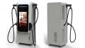
EV Charging Mode 4
This is the only charging mode that incorporates an off-board charger with a DC output. The DC current is delivered directly to the battery and the on-board charger is bypassed. This mode can provide 600 V DC with a maximum current of 400 A. The high power level involved in this mode mandates a higher level of communication and stricter safety features.
Mode 4 only allows a case C connection, where the charging cable is permanently connected to the charging station.

Mode four in a class C connection. Image used courtesy of Ali Bahrami
Conclusion
The IEC 61851 standard deals with electric vehicle conductive charging systems. The standard describes four different charging modes—modes 1–4.
The first three modes deliver AC current to the EV on-board charger; however, mode 4 delivers DC current directly to the battery and bypasses the on-board charger. Mode 3 employs several control and protection functions with the goal of public safety. We examined the control pilot circuit of this mode in greater detail in this article.