 Facebook
 Google
 GitHub
 Linkedin
High-Voltage DC Power Transmission: Should HVDC Replace AC in Power Systems?
Is AC energy transmission the most efficient option for the 21st century?
Is AC energy transmission the most efficient option for the 21st century?
AC energy transmission is the most common mode of energy transmission in the world. DC transmission can be found only in some specific applications.
The advantages and disadvantages of HVDC energy transmission should be analyzed in detail. Only then can we raise the question: Is AC energy transmission the most efficient way for the 21st century?
Nowadays, various requirements on increasing efficiency and reliability of transmission may lead us to question the usage of alternating current (AC) transmission systems. Intensive research of direct current (DC) systems is being performed because disadvantages of AC voltage systems are becoming visible.
The Historical Background of AC and DC Systems
The first electrical power system was built and tested at the end of the 19th century. In the beginning, DC power systems were primarily used. The DC power transmission system had several limitations. DC voltage could not be transformed, meaning that energy could not be transmitted long-distance without high voltage drop values and power losses.
Thomas Alva Edison and his team developed the DC generator, circuit breaker equipment, fuses, bulbs, and the first DC systems in 1881. The DC systems operated with 110 volts as small isolated systems to decrease power losses. Several years later (in 1887), George Westinghouse bought Tesla’s patents related to AC systems and employed him to continue its development.
The possibility of voltage transformation from one level to another made AC systems favorable for long-distance energy transmission. That was the main reason for them surpassing DC energy systems.
Nowadays, DC systems are used in some specific applications, such as telecommunication systems, vehicles, ships, and high-voltage transmission.
Limitations of Three-Phase AC Transmission Systems
A development of three-phase AC transmission systems is approaching the limits of its possibilities.
Such limits may include:
- Transmission power losses due to the inevitable reactive power transmission
- Increased power losses due to the skin effect
- The impossibility of interconnection ramified three-phase transmission systems with a different nominal frequency (50-60 Hz) or with a different frequency regulation method
- Increasing the short circuit current value (circuit breakers break faulty currents with difficulty; significant mechanical stress on electrical equipment)
- The impossibility of using longer cable lines (i.e., submarine cables) due to high transversal capacity values
Because of these AC transmission system limitations, the future of the energy transmission systems could be found in technologies based on using power electronics devices, known as HVDC transmission systems. The working principle of this system consists of AC power conversion into DC (by using rectifiers), long distance dc power transmission lines and DC power conversion into AC (by using inverters). The power conversion is performed in converter stations.
HVDC System Configuration
Essentially, there are two main elements of a high-voltage direct current (HVDC) system:
- Converter stations at the endpoints of the transmission system
- Transmission lines (overhead lines, cables)
Converter stations are able to operate in both regimes as inverters or as rectifiers. This feature enables energy transmission in both directions.
The converter station is an innovative solution which basically enables the HVDC system application. The most important parts of the converter station are the bridge converter unit and the converter transformer. A semiconductor valve is the main component of the bridge converter unit. An uncontrollable semiconductor valve is made of diodes while the controllable version is made of thyristors connected in a series configuration.
High-performance thyristors embedded in a modern HVDC system have a disk diameter ranging up to 5 inches (125 mm) with a maximum current of 4 kA and a blocking voltage capability above 8 kV. The thyristors can be connected in series configurations to get higher blocking capability with voltages above 100 kV.
Modern HVDC systems mostly use twelve-pulse bridge converters. They are designed as two fully-controllable six-pulse bridge converters connected in a series configuration, as seen below in Figure 1(a).
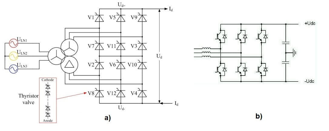
Figure 1. (a) Twelve-pulse bridge converter with two transformers secondary sides (Y-Y and Y-Δ) and (b) PWM HV converter. Click to enlarge
The Introduction of Pulse-Width Modulation
A development of high-frequency components, such as an IGBT, resulted in HV converter design which uses PWM (pulse width modulation) technology. By using PWM HV converters, it is possible to regulate any frequency and amplitude by changing PWM signals.
The main part of the PWM HV converter is IGBT bridge converter. The modern IGBT has a blocking voltage capability of 6.5 kV (though the latest research has enabled over 8 kV) with a maximum current value of 3.6 kA and a switching frequency that may range in the several tens of kHz. These IGBT converters are resistant on the critical dv/dt value higher than 100 kV/µs, as seen in Figure 1(b).
HVDC Transformers
HVDC transformers are an important part of an HVDC system. They are employed to transform voltage from an AC system to a corresponding AC voltage value for bridge converter input. The twelve-pulse bridge converter requires the supply designed by two three-phase voltage systems shifted by 30°. This is accomplished by using two three-phase transformers (or a transformer with two secondary sides as seen in Figure 1) with different winding configurations: one connected in Y-Y and the other in the Y- Δ transformer vector group.
This solution helps to cancel fifth and seventh harmonics from the AC side and sixth harmonic from the DC side, which results in a significant saving in harmonics filters.
Converter stations contain other important equipment such as AC filters, DC filters, surge arresters, disconnectors, etc.
HVDC Transmission Systems
HVDC transmission system advantages include:
- Decreased power losses (the influence of lines parasitic inductance is insignificant)
- Almost full transmission capacity used for active power transmission
- A lower number of lines for transmitting the same amount of energy
- A lower line cross section value (insignificant skin effect)
- A less expensive tower and transmission route due to a smaller number of lines (as illustrated in Figure 2, below)
- Submarine long-distance energy transmission due to low transversal capacity values

Figure 2. The HVDC transmission towers takes up less space
On the other hand, HVDC transmission systems do face some disadvantages, such as:
- Inverter operations produce a significant level of high harmonics in the network and create issues with power quality
- Also, power electronics produce noise in telecommunication signals. This may be mitigated by the development of filters which help decrease the influence of such disadvantages.
- Converter stations consist of a huge number of thyristors, which are an expensive power electronics component.
- There are also significant power losses during thyristor operation.
Additionally, it should not be forgotten that almost all electrical infrastructure and energy consumers are adapted to AC power, requiring a shift.
The Economic Aspect of HVDC Transmission Systems
The cost-effectiveness of HVDC transmission systems depends on several factors.
The main factor is the transmission distance. In the case of a shorter transmission distance, it is efficient to install HVAC transmission systems. For long-distance lines, however, the HVDC systems are cost-effective. It is hard to find the critical distance at which the HVDC system installation become justified. Just for the purpose of orientation, the critical distance for an overhead power transmission system is between 300 and 500 miles with a transmission power of 2000 MW.
The cost of the HVDC system is high because of a converter station installation in the transmission system endpoints. The cost of the HVAC system is significantly lower in those system parts.
Here are some hypothetical situations wherein a decision in favor of an HVDC transmission system might be made:
- When the HVDC transmission system is cost effective compared to the three-phase HVAC system (e.g., high transmission power, long power transmission distance)
- When the HVAC system is not possible (e.g., interconnections of the asynchronous three-phase AC power network, long cable lines as submarine power transmission)
- When the power regulation and power flow control is required even if the HVAC transmission is cost-effective
What's your experience with power systems? Do you agree with this assessment of AC vs DC systems? Share your expertise in the comments below.


No.
I enjoyed this highly informative article, but I’ll bet it Nicola Tesla up in EE heaven did not ☺
Although HVDC has a few applications, you won’t see this become a new trend. A major limitation is availability of a HVDC circuit breaker. In order to interrupt a high-voltage, high-current circuit, you must introduce a current zero crossing point. The HVDC circuit breakers add components creating a transient which produces the current zero where a breaker can interrupt it. Cost of breakers and other HVDC components relegate use of HVDC to a few special applications.