Facebook
 Google
 GitHub
 Linkedin
Preserving Battery Life: Waking the FPB-RA0E1 from Low-Power Mode Using a 32-Bit Interval Timer
This article shows you how to configure Software Standby mode and implement a periodic wake-up routine on the Renesas FPB-RA0E1 Fast Prototyping Board, built around the Arm Cortex-M23-based RA0E1 MCU.
You have designed a remote sensor, and power efficiency is the only thing keeping it running in the field. However, putting a microcontroller into deep sleep is only useful if it can reliably wake itself up without an external trigger. A hardware interval timer solves this issue by acting as an ultra-low-power alarm clock, ensuring the board wakes up exactly when needed to take its next reading.
This article shows you how to configure Software Standby mode and implement a periodic wake-up routine on the Renesas FPB-RA0E1 Fast Prototyping Board, built around the Arm Cortex-M23-based RA0E1 MCU. Using the e² studio IDE and the Flexible Software Package (FSP), you'll configure the 32-bit Interval Timer (r_tml) as a wake source, calculate precise delay periods, and measure physical current draw to verify your power savings. In the real world, this exact power-cycling strategy allows IoT nodes and battery-powered instruments to operate for years without maintenance.
Project Specs
| Target Board | FPB-RA0E1 Fast Prototyping Board |
| MCU Family | Renesas RA0 Series |
| Peripheral Covered | Low Power Modes (r_lpm) and 32-bit Interval Timer (r_tml) |
| IDE / Toolchain | e² studio + FSP |
| Interface Used | Digital Multimeter (for current measurement) |
| Baud Rate | N/A |
| Skill Level | Intermediate |
| Build Time | 25 minutes |
| Prerequisites | e² studio installed, board initialized, basic multimeter operation |
Why Controlling Power Modes Matters
Without a strategy to minimize power consumption, a microcontroller running at full clock speed will quickly drain a battery. By transitioning the processor into Software Standby mode, you can shut down the main CPU and non-essential peripherals, slashing current draw from milliamps to microamps.
The 32-bit Interval Timer (TML32) remains active during this deep sleep because it runs off a separate, low-speed oscillator. This technique is crucial for applications like environmental data loggers, smart meters, and portable medical devices, where the system spends 99% of its life asleep. For more advanced implementation strategies, check out the RA0 Series Low Power Consumption Guide.
What You'll Need
Hardware
- Renesas FPB-RA0E1 Fast Prototyping Board
- Digital Multimeter (with ammeter capabilities)
- Micro USB cable
- Jumper wires
Software
The Concept in 60 Seconds
Software Standby mode halts the CPU core and most high-speed clocks, preserving only the SRAM contents and a few critical low-power peripherals. The 32-bit Interval Timer is one of these exceptions. By clocking this timer with the Low-Speed On-Chip Oscillator (LOCO), it continues counting while the rest of the board sleeps. When the timer's counter matches a pre-calculated period, it generates a hardware interrupt. The MCU detects this interrupt, wakes up, restores its main clocks, and resumes executing code exactly where it left off.
Step-by-Step: Building the Project
Step 1: Add the Low Power Mode Stack
- Create a new C/C++ project for the FPB-RA0E1.
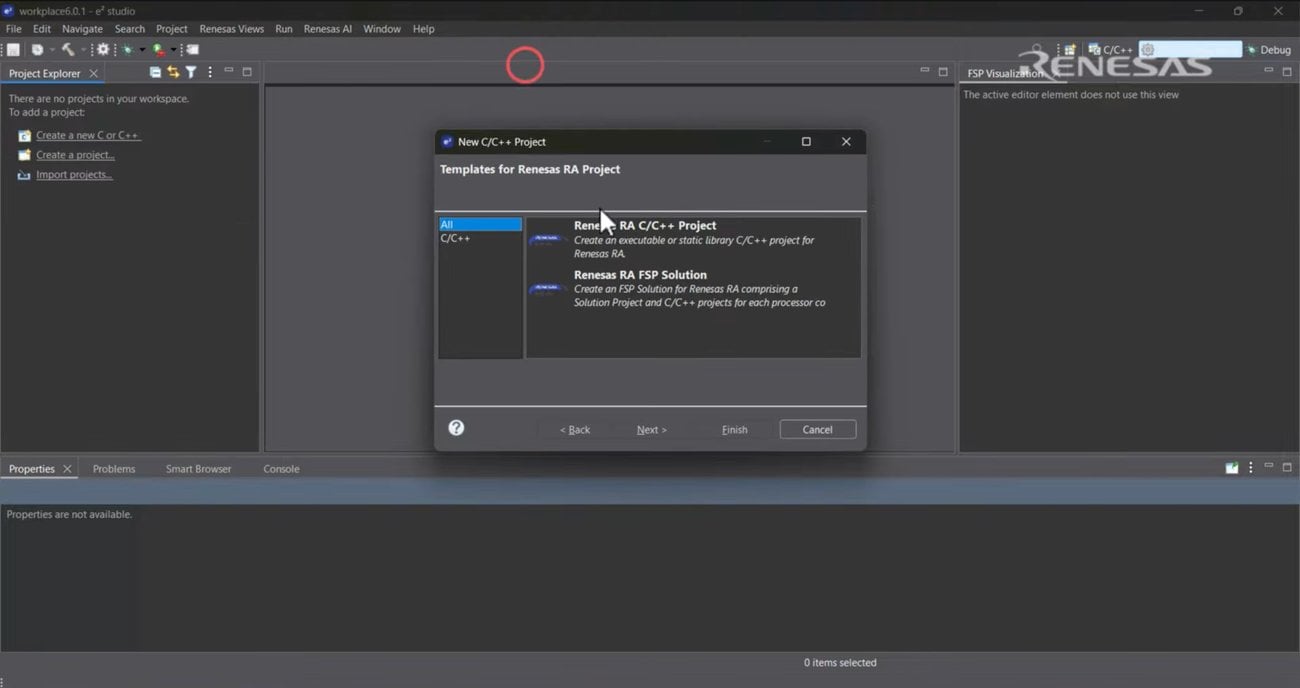
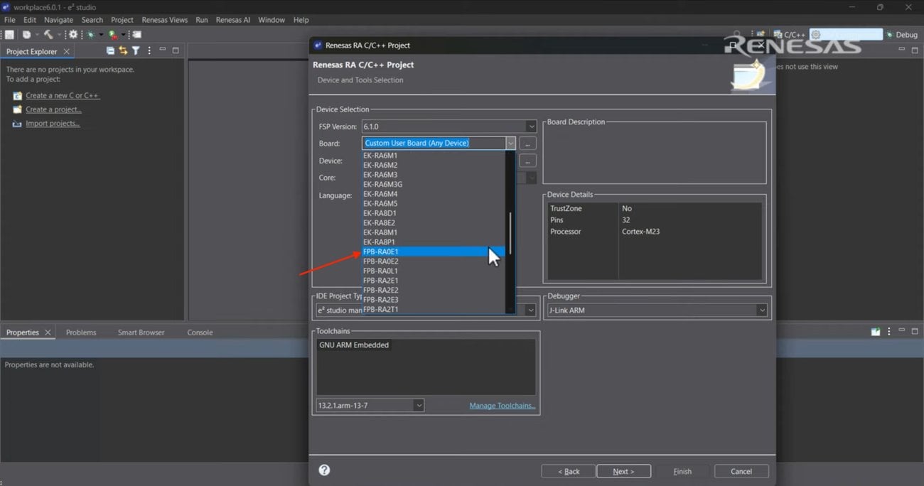
- Open your FSP Configuration, navigate to the Stacks tab, and add the Low Power Modes (r_lpm) stack. Doing this primes the power management controller to handle deep sleep transitions.
Step 2: Configure the Wake Source
- In the properties for the Low Power Mode stack, set the Low Power Mode to Software Standby mode.
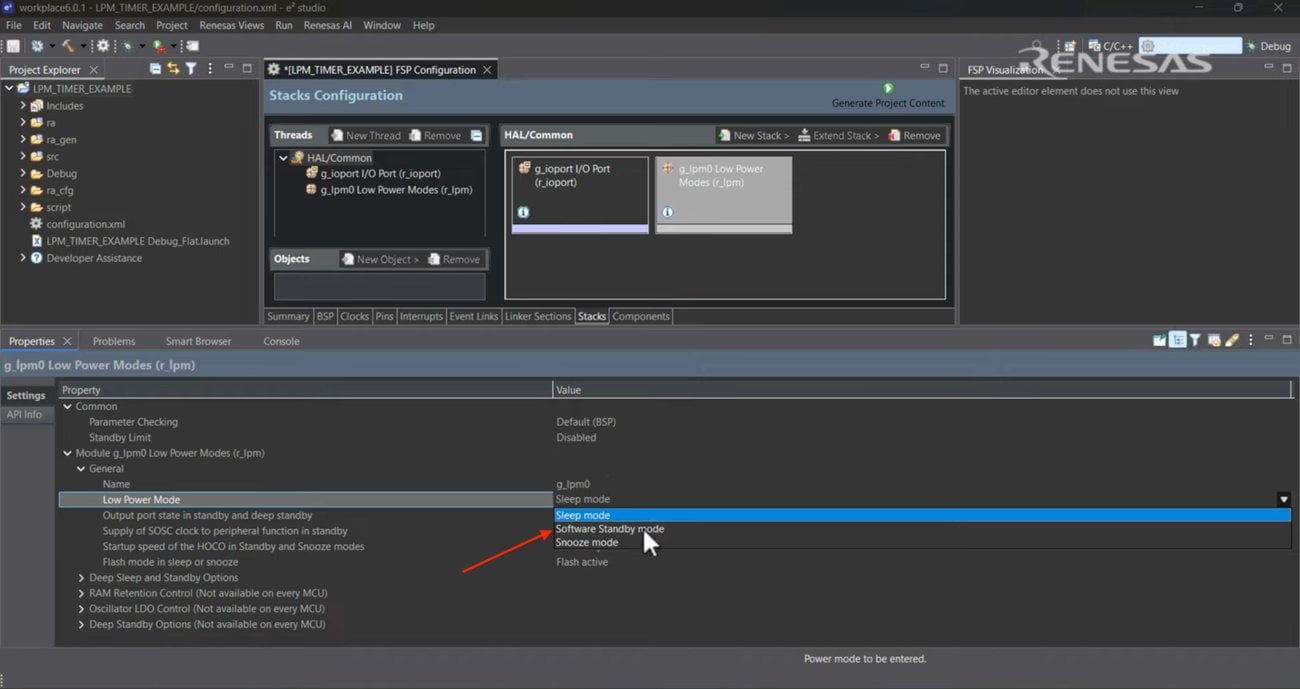
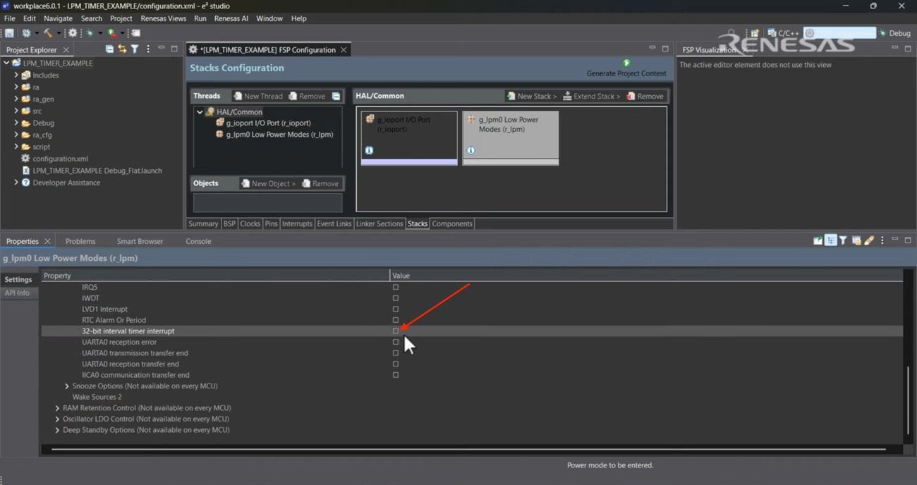
- Scroll down to the Wake Sources and check the box for 32-bit interval timer interrupt. This step tells the core exactly which signal is allowed to interrupt its slumber.
Step 3: Add the 32-Bit Interval Timer
Return to the Stacks tab and add the 32-bit Interval Timer (r_tml) stack. In properties, ensure it is set to 32-bit Counter Mode and assign any valid interrupt priority (we use 2 here).
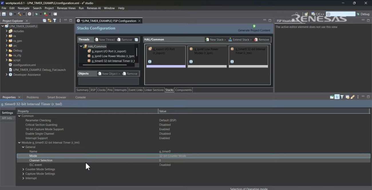
Note: The 32-bit interval timer interrupt must be enabled to pull the processor out of standby. (This is the same signal you enabled as a wake source in Step 2, generated when the counter reaches the period you set with R_TML_PeriodSet.) You'll need to assign it a valid priority in the configurator (any level, including priority 0), provide a callback, and enable Interrupt Support in the r_tml build settings. What matters is that the priority field is set at all, not that it exceeds any specific value.
Step 4: Route the Low-Power Clocks
- Navigate to the Clocks configuration tab. Set the TML FITL0 Src selector to LOCO (Low-Speed On-Chip Oscillator).
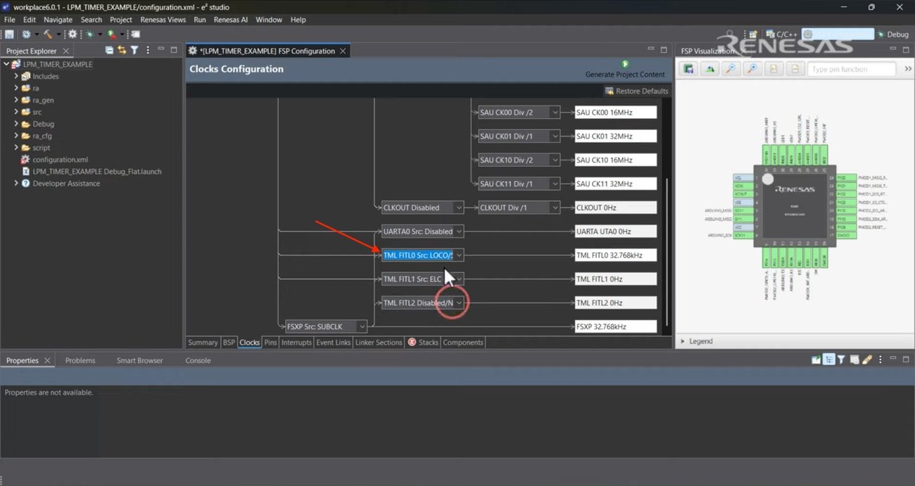
FITL0 is a configurable input. It can be driven from HOCO, MOCO, MOSC, or LOCO/SOSC, but only the LOCO or the sub-clock oscillator (SOSC) keeps running in Software Standby. Routing the timer's count clock through LOCO ensures that it keeps ticking after the power-hungry, high-speed clocks are shut off during sleep.
- In the BSP tab, set the Subclock Drive to Low power mode 2 to optimize efficiency.
Step 5: Initialize Peripherals in Code
- Generate your project content and open hal_entry.c.
- Drag the R_LPM_Open and R_TML_Open API calls from Developer Assistance into your code before the main loop. Initializing these modules locks your FSP GUI configurations to the underlying hardware registers.
Step 6: Calculate the Wake Interval
Define a target sleep time variable (for example, 15 seconds). Use R_TML_InfoGet to retrieve the timer's clock frequency and multiply this frequency by your target time to determine the total period counts. Calculating this dynamically prevents timing bugs if you alter the oscillator speed later. 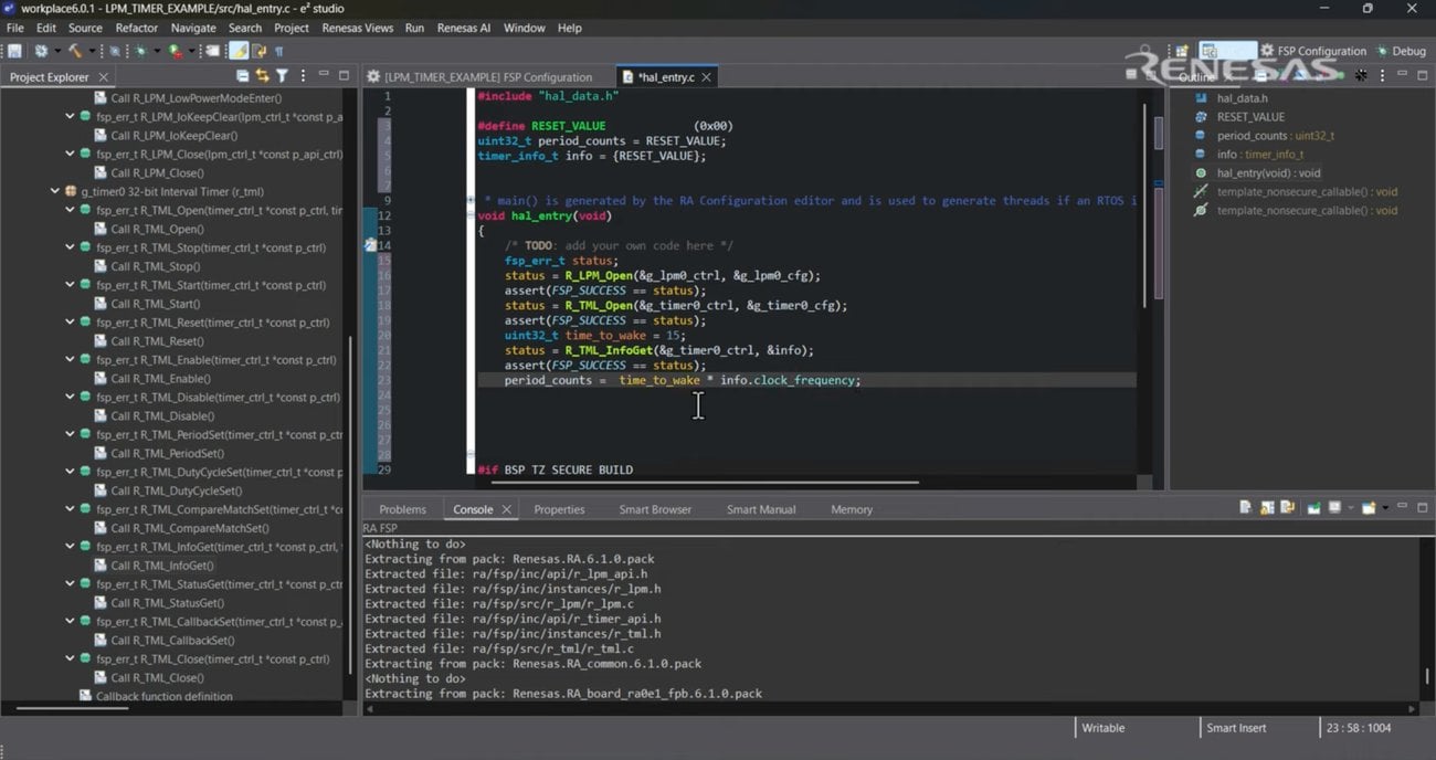
Step 7: Execute Sleep Logic
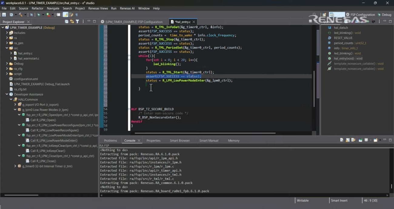
- Inside your execution loop, configure onboard LEDs to blink using R_IOPORT_PinWrite to prove the board is awake. Stop the timer, update its period with R_TML_PeriodSet, and start the timer.
- Finally, call R_LPM_LowPowerModeEnter. The processor halts on this enter command and only resumes when the timer fires 15 seconds later.
Step 8: Build and Measure
- Build the project and flash it to the evaluation board.
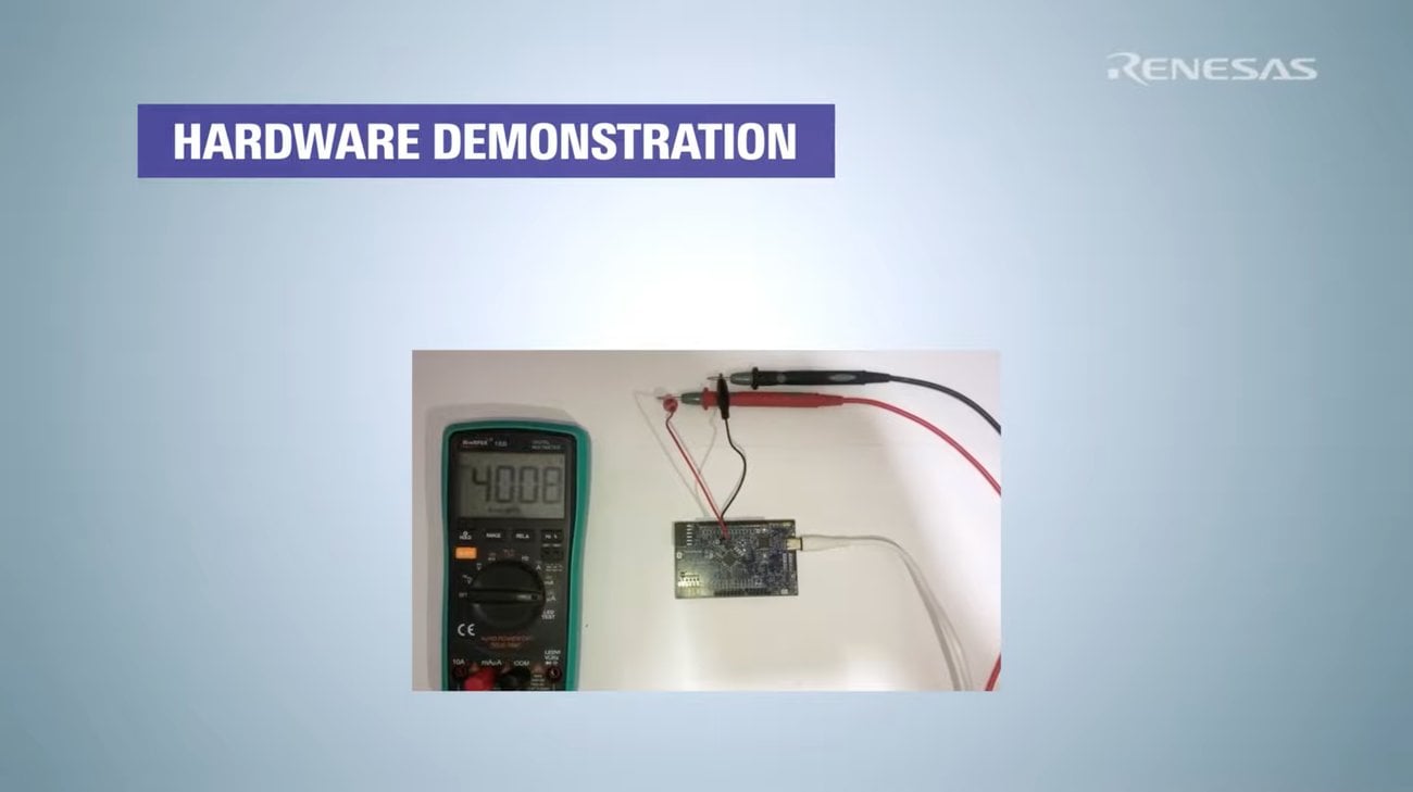
- Connect your multimeter in series with the board to measure current. Physical measurement is the only way to prove the hardware actually achieved microamp sleep states.
Code Snippet
// Calculate the exact number of counts required for a 15-second sleep
period_counts = time_to_wake * info.clock_frequency;
// Stop the timer, update its period, and restart counting
R_TML_Stop(&g_timer0_ctrl);
R_TML_PeriodSet(&g_timer0_ctrl, period_counts);
R_TML_Start(&g_timer0_ctrl);
// Transition the MCU into Software Standby mode
R_LPM_LowPowerModeEnter(&g_lpm0_ctrl);
// Execution pauses here. The MCU will wake up on the timer interrupt.
What You Should See
When the board is actively blinking its LEDs, your ammeter will read approximately 4.0 mA, indicating normal execution. After the blinking sequence finishes, the LEDs will turn off, and the current draw will drop drastically to roughly 32 µA as the board enters Software Standby mode. Exactly 15 seconds later, the current spikes back to 4 mA, and the LEDs will resume blinking.
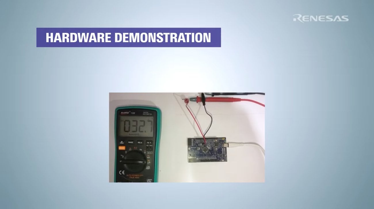
Multimeter reading of approximately 32 µA during Software Standby mode. Image courtesy of Renesas.
Troubleshooting
The current draw doesn't drop during the sleep phase.
Verify that all unused GPIO pins are configured correctly and not floating. Ensure the active LEDs are written to a low state before calling the low power enter function.
The board goes to sleep but never wakes up.
Confirm that the 32-bit interval timer interrupt is enabled. It needs a valid priority assigned in the configurator (any level, including 0), a callback function, and Interrupt Support turned on in r_tml build settings. A blank priority field, not a low one, is the usual culprit. Check your Clocks tab to confirm the FITL0 source is routed to LOCO (or SOSC), a source that keeps oscillating in Software Standby.
The sleep duration is inaccurate.
Double check your period count calculation. Make sure you are multiplying the target time in seconds by the precise clock frequency returned by the R_TML_InfoGet function, rather than hardcoding a guessed clock speed.
Where to Take It Next
Now that you have verified extreme low-power sleep capabilities, you could try integrating an external interrupt. You can configure a push-button on an IRQ pin as a secondary wake source, allowing the board to wake either when the timer expires or when a user presses a button. You can also explore writing telemetry data to flash memory just before the board sleeps, which is critical for continuous data logging. For a closer look at clock configurations, consult the RA0E1 Group Hardware User's Manual.
Frequently Asked Questions
Why use the 32-bit Interval Timer instead of a standard PWM timer for sleep mode?
Standard timers typically rely on high-speed peripheral clocks that must be shut down during Software Standby mode to save power. The 32-bit Interval Timer is specifically designed to run on ultra-low-power oscillators like the LOCO while the rest of the system sleeps.
What is LOCO?
The Low-Speed On-Chip Oscillator (LOCO) is an internal clock source designed for extreme power efficiency. It runs independently of the main high-speed clocks.
Why do I need an ammeter for this project?
Software debuggers cannot actively monitor the processor while it is in deep sleep states as the debug interface itself loses access or clocking. You'll need a physical ammeter to confirm that the hardware is dropping into the microamp range.
Can I wake the board using external sensors?
Yes. In addition to internal timers, the Low Power Mode stack allows you to configure external IRQ pins as wake sources, which is useful for triggering wakeups from external I²C sensors or motion detectors.
Related Resources
- Renesas FPB-RA0E1 Product Page
- FSP Documentation
- Renesas RA Family page
- RA0E1 Group Datasheet
- Hardware User's Manual
- RA0 Series Low Power Consumption Application Note
- RA0 Quick Design Guide
Related Content