 Facebook
 Google
 GitHub
 Linkedin
Radio Meets Fiber Optics: RF Over Fiber
Radio Over Fiber (ROF) combines RF and optics, providing optical links to replace strategic portions of cellular, satellite, and copper based systems.
Learn about what ROF (radio/RF over fiber) is and how it works, as well as its flaws and benefits.
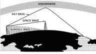
Two technologies with tremendous impact have been wireless and fiber-optic communications. Using radio frequency (RF) signals, wireless has given us military radar, avionics, cellular and satellite communications; our world is safer and more interesting thanks to all the benefits provided by wireless breakthroughs. We no longer need to be ‘homebased’ for an expected call or to catch a podcast; our banking, fitness routines, transportation, communications and home security can all be scheduled and controlled from our mobiles.
With strands of cladded glass as their backbone, fiber-optic networks provide the capacity to carry lots of data thanks to their huge bandwidth. In landline telecommunications and cable television (CATV) distribution, fiber-optic networks have taken over from copper wire, carrying telephone conversations and specialized content more efficiently and with better reliability. They enable our varied entertainment selections and allow our devices to be part of the internet.
Linking these two technologies is RF Over Fiber (RFOF), also referred to as Radio Over Fiber (ROF).
ROF is an analog transmission that uses RF signals to modulate light which is transmitted over a fiber-optic cable. At the receiving end, the RF energy is recovered. The optical link provides a high bandwidth, low-loss communications link to transport RF energy at optical frequencies, then the RF signal is recovered for use at the load point.
Traditional RF Transmission Line
The traditional transmission line for RF signals is coaxial cables (coax). The history of coax has familiar names: Oliver Heaviside (credited with reformatting Maxwell's Equations), Nikola Tesla and the Bell Laboratories of AT&T. The physical construction of coax allows RF energy to be transported within its shields. That we still use cables with origins in the late 1880s attests to their usefulness.
Still, with its copper centers and dielectrics, there is some rigidity and weight to coax. Its bandwidth is limited, it has losses, and is susceptible to noise, radio frequency interference (RFI) and electromagnetic interference (EMI). Coax has always had limitations due to its physical components; if it is bent too much, the shielding is interrupted; moisture degrades it over time.
While light has been used in communications going back to Alexander Graham Bell’s photophone, to carry signals more than a few feet required the development of low-loss glass cables and the semiconductor laser. By the 1980s, fiber-optic networks were being used for cable television (CATV), replacing coax and microwave links.

Figure 1. The ROF optical link
As shown in Figure 1, ROF takes an RF signal and processes it through an optical link. The optical link consists of:
- A light source to act as an optical carrier, usually provided by a laser diode. This semiconductor laser is controlled by forward-biasing the semiconductor junction. Due to the physical properties of fiber-optic cable, certain frequencies have less attenuation. The optical frequencies used most often are:
- LED: 780nm, 850nm, 1300nm
- Laser: 1310, 1550nm, 1625nm
- An electrical-optical modulator (E/O), to convert/modulate the light beam using the RF signal. Intensity modulation is used; these transducers have a signal controlled element that modulates the beam of light. The RF signal can be used to directly modulate the light source, or an intermediate frequency can be used. Modulation bandwidths can approach the gigahertz range.
- The optical transmission medium: a single-mode fiber-optic cable. Single-mode has a lower number of light reflections, which lowers attenuation and allows the signal to go further than multimode. Doped optical fibers, like erbium doped cables, provide amplification by pumping the core of the fiber to produce gain.
- An optical-electrical modulator (O/E) to recover the RF signal at the receiver side, usually a photodiode or avalanche photodiode (APD). These components produce a current as a result of the absorption of photons that is proportional to the intensity of the received light.
At this point, the original RF signal is recovered.
Wavelength Division Multiplexing (WDM) and Dense Wavelength Division Multiplexing (DWDM) are used to maximize capacity. These multiplexing techniques combine separate optical signals on different wavelengths for transmission via a single light. The combined signal is then split to recover the separate optical signals after transmission, as shown in Figure 2.

Figure 2. An example of an ROF link
The Benefits of Radio Over Fiber
ROF reduces RFI/EMI. Avionics requires control and communication equipment to reside in localized areas. Replacing coax in aircraft not only prevents RFI/EMI but its lightweight construction removes the weight of the coax.
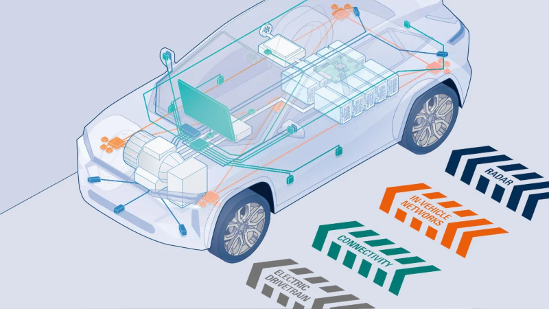
ROF eases spectrum constraints. Additional RF spectrum can't be manufactured like fiber-optic cables. Using ROF in buildings and stadiums relieves congestion and uses available spectrum effectively. Emerging technologies, such as self-driving cars, are considering ROF for control and communications.
ROF replaces multiple coax cables. With advanced mobile offerings, multiple antennas may be required to provide service and coverage at each cell tower. ROF replaces multiple coax cables with a single fiber-optic cable. Fiber to the antenna (FTTA) systems, shown in Figure 3, incorporate the required control at the antenna.

Figure 3. ROF FTTA
ROF transports RF efficiently. Satellite systems physically position receivers where the best reception is possible then transport the signals to their control hubs. ROF replaces long coax runs, efficiently carrying RF signals over long distances without the use of additional amplifiers. The low attenuation of fiber-optic cable removes the need for multiple connections needed with coax.

Figure 4. ROF distribution
ROF enhances cell coverage. It extends cell coverage where RF signals aren't possible due to geography and reach. Figure 5 shows ROF continuing cell coverage when a tunnel would normally result in a dead zone. The ROF link enables network access within the tunnel, much like networks within buildings.

Figure 5. Enhanced cell coverage via ROF
Technical Issues and Future Challenges of ROF
The characteristics of a communication link still have to be considered.
The gain, noise figure (NF), and dynamic range (DR) of the fiber-optic link is as important as in electrical communications. The source of the noise is different: the laser's phase noise, the photodiode's shot noise. There's also thermal noise. The length of cable may be limited due to chromatic dispersion and phase decorrelation. As in all analog transmissions, impedance matching is required at the transmitter and receiver to attain maximum power transfer.
The initial installation of the ROF links is more involved than when using coax. If the fiber optic link is severed, repairs typically take longer.
Handling these technical issues means additional circuits and control within the system and add to the expense of installing ROF links. The benefits of ROF ensure that research will continue to address any limiting factors.
Summary
As the RF spectrum becomes constrained, engineers are searching for alternatives to deliver content. ROF provides coverage in dead zones and provides an alternative to acquiring spectrum for emerging technologies. ROF is immune to RFI/EMI and can replace long coax runs to effectively transport RF energy.


informative…