Facebook
 Google
 GitHub
 Linkedin
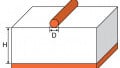
Microstrip Trace Width Calculator
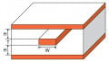
This tool is designed to compute for the trace width of a microstrip
Outputs
Overview
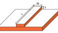
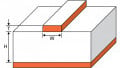
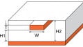
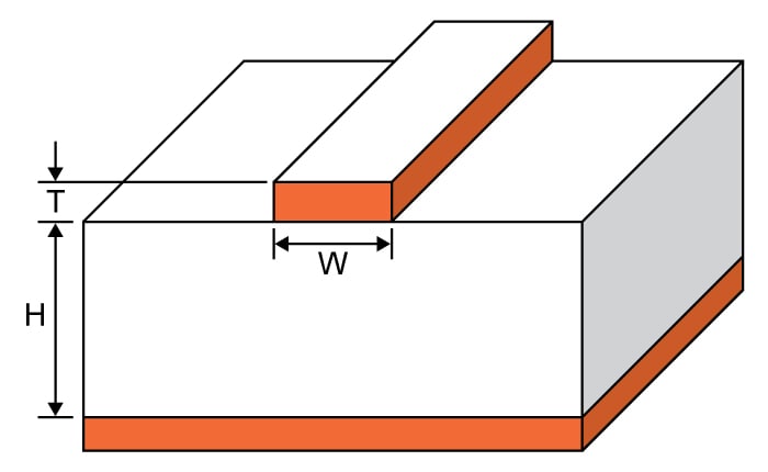
The maximum current that a microstrip can handle is a function of its width. This is the reason why engineers specify the trace width in their designs. This calculator computes the trace width of a microstrip given the following information: maximum current, trace thickness, temperature rise, ambient temperature, and length. This tool will also compute the resistance of the microstrip, the voltage drop, and the power dissipation.
Equations
$$W = \frac{A}{1.378T}$$
Where:
$$A$$ = area = $$\frac{I}{(k\Delta T^{b})^{\frac{1}{c}}}$$
Note:
For internal layers: k = 0.024, b = 0.44, c = 0.725
For external layers: k = 0.048, b = 0.44, c = 0.725
where k, b, and c are constants resulting from curve fitting of IPC-2221 data
Applications
Microstrips are simply PCB traces whose dimensions are carefully calculated to achieve a desired circuit operation. These devices are often found in systems involving microwave frequencies. Microstrips are used at very high frequencies because the required circuit inductance and capacitance values are too small for standard capacitors and inductors. Without microstrips, it is quite challenging to manufacture capacitors and inductors at very high frequencies.
Just like the standard capacitor and inductor, the microstrip is also subject to maximum ratings. This calculator uses the relationship between the ampacity of a conductor and its dimensions. A wider trace means a lower resistance which is equivalent to a higher current. But a conductor has its limits when it comes to the current it can handle, which means there is also a limit to how wide the trace of a microstrip can become.