 Facebook
 Google
 GitHub
 Linkedin
Embedded Microstrip Impedance Calculator
This calculator helps you compute the characteristic impedance of an embedded microstrip.
Output
Overview
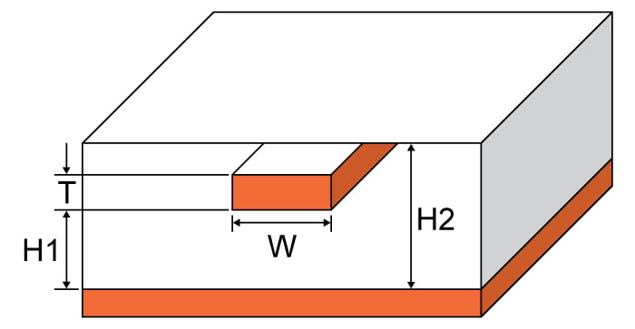
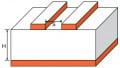
This calculator is designed to calculate the characteristic impedance of an embedded microstrip - a flat conductor suspended over a ground plane with a dielectric between it and another dielectric material above the conductor (see diagram below). Embedded microstrips are commonly crafted using printed circuit boards, although other materials can be used. An embedded microstrip can be constructed using a microstrip with a solder mask.
Just enter the given values for trace thickness, substrate heights, trace width and subtrate dielectric in the calculator above and press the "calculate" button. The default units for all given values, except the subtrate dielectric, is in millimetres. It is possible to select other units. Note: height H1 cannot be greater in value than height H2. The calculator will give zero if this is the case.
Equations
$$Z_{0_{embed}}=Z_{0}\left \{ \frac{1}{\sqrt{e^{\frac{-2b}{H_{1}}}}+\frac{er}{Z_{0surf}e_{reff}}(1-e^{\frac{-2b}{H_{1}}})} \right \}$$
Where:
$$er_{eff}=\frac{er+1}{2}+\frac{er-1}{2}\left \{ \sqrt{\frac{W}{W+12H_{1}}}+0.04(1-\frac{W}{H_{1}})^2 \right \}$$ when $$\frac{W}{H_{1}} < 1$$
$$er_{eff}=\frac{er+1}{2}+\frac{er-1}{2}\left \{ \sqrt{\frac{w}{w+12h_{1}}}\right \}$$ when $$\frac{W}{H_{1}} ≥ 1$$
$$W_{eff}=W+\left ( \frac{t}{\pi } \right )ln\left \{ \frac{4e}{\sqrt{(\frac{T}{H})^2+(\frac{T}{W \pi+1.1T\pi})^2}} \right \}\frac{E_{r}+1}{2E_{r}}$$
$$X_{1}=4(\frac{14E_{r}+8}{11E_{r}})(\frac{H_{1}}{W_{eff}})$$
$$X_{2}=\sqrt{16(\frac{H_{1}}{W_{eff}})^2(\frac{14E_{r}+8}{11E_{r}})^2+(\frac{E_{r}+1}{2E_{r}})\pi^2}$$
$$b = H_{1} - H_{2}$$
$$Z_{0_{embed}}$$ = characteristic impedance of the embedded microstrip in ohms (Ω).
$$H_{1}$$ = subtrate height 1
$$H_{2}$$ = subtrate height 2
$$W$$ = trace width
$$T$$ = trace thickness
$$\epsilon_{r}$$ = substrate dielectric
$$er_{eff}$$ = effective substrate dielectric
Source: PC-2141A (2004) “Design Guide for High-Speed Controlled Impedance Circuit Boards”
Applications
The embedded microstrip has a similar construction to the microstrip except for the additional dielectric subtrate on top of the conductor. Microwave antennas and couplers as well as some filters can be created using the embedded microstrip. These transmission lines are not as easy to manufacture as microstrips, but nevertheless are still far cheaper than the traditional waveguide, as well as being more compact and lighter. However, microstrips cannot handle power levels as high as waveguides can. Microstrips also have issues in power loss, cross-talk and unintentional radiation because they are not enclosed like the waveguide.
Embedded microstrips also find themselves in high-speed digital PCB designs where entails signal travel with minimal distortion and no cross-talk and/or radiation is required.


Hello. The equations listed on this page look promising but any detailed look brings up questions:
- is “H” H1 or H2? It may be presumed that h1 and H1 line up but that is assumption not certainty
- is “Er” the same as dielectric constant? Or effective dielectric constant?
The calculator brings up answers but there is no error checking, or at least not enough. H1 can be greater than H2 and still yield an answer.
Can anyone list the original source of these equations or provide a consistent set of them?
Thank you in advance.
Hello
Can you update this calculator using the IPC-2141A(2004) Errata ?
http://www.ipc.org/4.0_Knowledge/4.1_Standards/2141A_Errata.pdf
Thanks
In the Embedded Microstrip Impedance Calculator: What is the time delay per unit length for the calculated structure. This calculator is not complete without this additional result. Thanks for making this available. Also, like the previous two comments!