Bipolar Junction Transistors as Switches

Discrete Semiconductor Devices and Circuits

PDF Version
  • Question 1

    Solid-state switching circuits usually keep their constituent transistors in one of two modes: cutoff or saturation. Explain what each of these terms means.

    Reveal answer
  • Question 2

    Explain the function of this light-switching circuit, tracing the directions of all currents when the switch closes:
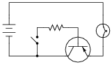


    Reveal answer
  • Question 3

    Trace the directions of all currents in this circuit, and determine which current is larger: the current through resistor R1 or the current through resistor R2, assuming equal resistor values.


    If switch SW2 were opened (and switch SW1 remained closed), what would happen to the currents through R1 and R2?

    If switch SW1 were opened (and switch SW2 remained closed), what would happen to the currents through R1 and R2?

    Reveal answer
  • Question 4

    Calculate all component voltage drops in this circuit, assuming a supply voltage of 15 volts, an emitter-base forward voltage drop of 0.7 volts, and a (saturated) emitter-collector voltage drop of 0.3 volts:


    Reveal answer
  • Question 5

    A student attempts to build a circuit that will turn a DC motor on and off with a very delicate (low current rating) pushbutton switch. Unfortunately, there is something wrong with the circuit, because the motor does not turn on no matter what is done with the switch:


    Correct the error(s) in this circuit, showing how it must be set up so that the transistor functions as intended.

    Reveal answer
  • Question 6

    A stepper motor is a special type of electric motor typically used for digital positioning systems. The motor shaft rotates by alternately energizing its coils in a specific sequence. These electromagnet coils draw a fair amount of DC current (several amperes is not uncommon for heavy-duty stepper motors), and as such are usually triggered by power transistors:


    The control circuit that usually sends pulse signals to the base of the power transistors is not shown in this diagram, for simplicity. Your task is to draw a pushbutton switch in this schematic diagram showing how the first motor coil could be manually energized and de-energized. Be sure to note the directions of currents through the transistor, so that your switch is installed correctly!

    Also, explain the purpose of the diode connected in parallel with the motor coil. Actually, there will be one of these diodes for each of the motor coils, but the other three are not shown for the sake of simplicity.

    Reveal answer
  • Question 7

    Some of the following transistor switch circuits are properly configured, and some are not. Identify which of these circuits will function properly (i.e. turn on the load when the switch closes) and which of these circuits are mis-wired:


    Reveal answer
  • Question 8

    Some of the following transistor switch circuits are properly configured, and some are not. Identify which of these circuits will function properly (i.e. turn on the load when the switch closes) and which of these circuits are mis-wired:


    Reveal answer
  • Question 9

    Some of the following transistor switch circuits are properly configured, and some are not. Identify which of these circuits will function properly (i.e. turn on the load when the switch closes) and which of these circuits are mis-wired:


    Reveal answer
  • Question 10

    In each of the following circuits, the light bulb will energize when the pushbutton switch is actuated. Assume that the supply voltage in each case is somewhere between 5 and 30 volts DC (with lamps and resistors appropriately sized):


    However, not all of these circuits are properly designed. Some of them will function perfectly, but others will function only once or twice before their transistors fail. Identify the faulty circuits, and explain why they are flawed.

    Reveal answer
  • Question 11

    Draw the necessary wire connections so that bridging the two contact points with your finger (creating a high-resistance connection between those points) will turn the light bulb on:


    Reveal answer
  • Question 12

    The ignition system of a gasoline-powered internal combustion automobile engine is an example of a transformer operated on DC by means of an oscillating switch contact, commonly referred to as the contact “points”:


    The cam-actuated “point” contacts open every time a spark is needed to ignite the air-fuel mixture in one of the engine’s cylinders. Naturally, these contacts suffer a substantial amount of wear over time due to the amount of current they must make and break, and the frequency of their cycling.

    This device was seen by automotive engineers as a prime candidate for replacement with solid-state technology (i.e., a transistor). If a transistor could take the place of mechanical “point” contacts for making and breaking the ignition coil’s current, it should result in increased service life.

    Insert a transistor into the following circuit in such a way that it controls the ignition coil’s current, with the “point” contacts merely controlling the transistor’s state (turning it on and off):


    Reveal answer
  • Question 13

    Electronic ignition systems for gasoline-powered engines typically use a device called a reluctor to trigger the transistor to turn on and off. Shown here is a simple reluctor-based electronic ignition system:


    Explain how this circuit functions. Why do you think the triggering device is called a “reluctor”? What advantage(s) does this circuit have over a mechanical “point” operated ignition system?

    Reveal answer
  • Question 14

    Predict how all component voltages and currents in this circuit will be affected as a result of the following faults. Consider each fault independently (i.e. one at a time, no multiple faults):


    Transistor Q1 fails open (collector-to-emitter):
    Transistor Q1 fails shorted (collector-to-emitter):
    Reluctor magnet weakens:
    Capacitor C1 fails shorted:
    Capacitor C1 fails open:
    Transformer (“coil”) T1 primary winding fails open:
    Transformer (“coil”) T1 secondary winding fails open:

    For each of these conditions, explain why the resulting effects will occur.

    Reveal answer
  • Question 15

    Predict how all component voltages and currents in this circuit will be affected as a result of the following faults. Consider each fault independently (i.e. one at a time, no multiple faults):


    Transistor Q2 fails open (collector-to-emitter):
    Transistor Q1 fails shorted (collector-to-emitter):
    Capacitor C1 fails shorted:
    Capacitor C1 fails open:
    Reluctor coil L1 fails open:

    For each of these conditions, explain why the resulting effects will occur.

    Reveal answer
  • Question 16

    Choose the right type of bipolar junction transistor for each of these switching applications, drawing the correct transistor symbol inside each circle:


    Reveal answer
  • Question 17

    Choose the right type of bipolar junction transistor for each of these switching applications, drawing the correct transistor symbol inside each circle:


    Also, explain why resistors are necessary in both these circuits for the transistors to function without being damaged.

    Reveal answer
  • Question 18

    In this circuit, the electric motor is supposed to turn on whenever the cadmium sulfide photocell is darkened:


    Unfortunately, though, the motor refuses to turn on no matter how little light strikes the photocell. In an attempt to troubleshoot the circuit, a technician measures voltage between the collector and emitter terminals of the transistor with the photocell covered by a piece of dark tape, and measures full battery voltage. The technician also measures voltage between the collector and base terminals of the transistor, and measures full battery voltage. At that point, the technician gives up and hands the problem to you.

    Based on this information, what do you suspect is faulty in this circuit, and how might you determine the exact location of the fault? Also, identify what you know to be not faulted in the circuit, based on the information given here.

    Reveal answer
  • Question 19

    The following circuit used to work fine, but does not work as it should anymore. The lamp does not come on, no matter what is done with the switch:


    The very first thing you do is use your multimeter to check for source voltage, TP4 to ground. Between those points you find 24 volts DC, just as it should be. Next you measure voltage between TP2 and ground with the switch pressed and unpressed. With the switch pressed, there is no voltage between TP2 and ground, but there is voltage (about 23.5 volts) when the switch is unpressed.

    From this information, determine at least two possible failures in the circuit which could cause the lamp not to energize, and also account for the voltage measurements taken.

    Reveal answer
  • Question 20

    What is the significance of a transistor’s beta (β) rating? What, exactly, does this figure mean? Explain how you might set up an experiment to calculate the beta of a given transistor.

    Obtain a copy of a datasheet for a small-signal transistor such as the 2N2222 and see what it has to say about that transistor’s beta. Note: the beta of a transistor may be represented by the Greek letter (β), or by a completely different symbolism known as a hybrid parameter: hFE

    Reveal answer
  • Question 21

    Explain what β means for a bipolar junction transistor, in your own words.

    Reveal answer
  • Question 22

    Write the mathematical formula defining β for a bipolar junction transistor:

    $$\beta =$$

    Reveal answer
  • Question 23

    An easy way to increase the effective current gain of a transistor is to “cascade” two of them in a configuration called a Darlington pair:


    Complete this schematic diagram, showing how a Darlington pair could be used to enable a cadmium sulfide (CdS) photocell to turn a motor on and off:


    Reveal answer
  • Question 24

    Calculate all labeled currents in this Darlington pair circuit (shown in this schematic in conventional flow notation), assuming a typical forward base-emitter junction voltage drop of 0.7 volts for each transistor:


    Reveal answer
  • Question 25

    Calculate all labeled currents in this Darlington pair circuit (shown in this schematic in conventional flow notation), assuming a typical forward base-emitter junction voltage drop of 0.7 volts for each transistor:


    Reveal answer
  • Question 26

    An alternative to the Darlington pair is the Sziklai pair, formed by a complementary pair of bipolar transistors:


    Complete the following circuits, showing how a switch would be connected to each of the transistor pairs to exert control over the electric motor:


    Reveal answer
  • Question 27

    Explain how the one toggle switch is able to switch both transistors on and off simultaneously in this motor control circuit:


    Reveal answer
  • Question 28

    Explain the operation of this “H-bridge” motor control circuit:


    At any given moment, how many transistors are turned on and how many are turned off? Also, explain what would happen to the function of the circuit if resistor R1 failed open.

    Reveal answer
  • Question 29

    Predict how the motor function in this circuit will be affected as a result of the following faults. Consider each fault independently (i.e. one at a time, no multiple faults):


    Transistor Q1 fails open (collector-to-emitter):
    Transistor Q2 fails open (collector-to-emitter):
    Transistor Q3 fails open (collector-to-emitter):
    Transistor Q4 fails open (collector-to-emitter):
    Resistor R1 fails open:
    Resistor R2 fails open:
    Resistor R3 fails open:
    Transistor Q3 fails shorted (collector-to-emitter):
    Transistor Q4 fails shorted (collector-to-emitter):

    For each of these conditions, explain why the resulting effects will occur.

    Reveal answer
  • Question 30

    The circuit shown here is part of a digital logic gate circuit:


    Logic circuits operate with their transistors either fully “on” or fully “off,” never in-between. Determine what state the LED will be in (either on or off) for both switch positions. You may find it helpful to trace currents and label all voltage drops in this circuit for the two switch states:


    For your voltage drop calculations, assume the following parameters:

    VCC = 5 volts
    VBE (conducting) = 0.7 volts
    VCE (conducting) = 0.3 volts
    Vf (regular diode conducting) = 0.7 volts
    Vf (LED conducting) = 1.6 volts
    Reveal answer
  • Question 31

    One of the simplest transistor “logic” circuits used in computer circuitry is the so-called inverter gate. Its logic diagram symbol is this:


    Inverters are often bundled six to a “DIP” (Dual-Inline Package) module, where all gates share the same two power supply connections (“Vcc” and “Ground”), like this:


    When constructed with bipolar junction transistors, the internal schematic diagram of a single inverter gate looks something like this:


    Being a digital logic circuit, it only “understands” two states: on and off. As you can see, a SPDT switch provides signal input into the logic gate, either full supply voltage (VCC) or no voltage at all (Gnd).

    Determine the voltage across the load resistance for each of these switch states. Based on your analysis, what is the logical function of an “inverter” gate?

    Reveal answer
  • Question 32

    There is a problem somewhere in this electronic ignition circuit. The “coil” does not output high voltage as it should when the reluctor spins. A mechanic already changed the coil and replaced it with a new one, but this did not fix the problem.


    You are then asked to look at the circuit to see if you can figure out what is wrong. Using your multimeter, you measure voltage between TP1 and ground (12 volts DC) and also between TP2 and ground (12 volts DC). These voltage readings do not change at all as the reluctor spins.

    From this information, identify two possible faults that could account for the problem and all measured values in this circuit, and also identify two circuit elements that could not possibly be to blame (i.e. two things that you know must be functioning properly, no matter what else may be faulted). The circuit elements you identify as either possibly faulted or properly functioning can be wires, traces, and connections as well as components. Be as specific as you can in your answers, identifying both the circuit element and the type of fault.

    Circuit elements that are possibly faulted
    1.
    2.
    Circuit elements that must be functioning properly
    1.
    2.
    Reveal answer
  • Question 33

    There is a problem somewhere in this electronic ignition circuit. The “coil” does not output high voltage as it should when the reluctor spins. A mechanic already changed the coil and replaced it with a new one, but this did not fix the problem.


    You are then asked to look at the circuit to see if you can figure out what is wrong. Using your multimeter, you measure voltage between TP1 and ground (12 volts DC) and also between TP2 and ground (0 volts DC). These voltage readings do not change at all as the reluctor spins.

    From this information, identify two possible faults that could account for the problem and all measured values in this circuit, and also identify two circuit elements that could not possibly be to blame (i.e. two things that you know must be functioning properly, no matter what else may be faulted). The circuit elements you identify as either possibly faulted or properly functioning can be wires, traces, and connections as well as components. Be as specific as you can in your answers, identifying both the circuit element and the type of fault.

    Circuit elements that are possibly faulted
    1.
    2.
    Circuit elements that must be functioning properly
    1.
    2.
    Reveal answer
  • Question 34

    Don’t just sit there! Build something!!


    Learning to mathematically analyze circuits requires much study and practice. Typically, students practice by working through lots of sample problems and checking their answers against those provided by the textbook or the instructor. While this is good, there is a much better way.

    You will learn much more by actually building and analyzing real circuits, letting your test equipment provide the “answers” instead of a book or another person. For successful circuit-building exercises, follow these steps:

    1. Carefully measure and record all component values prior to circuit construction, choosing resistor values high enough to make damage to any active components unlikely.
    2. Draw the schematic diagram for the circuit to be analyzed.
    3. Carefully build this circuit on a breadboard or other convenient medium.
    4. Check the accuracy of the circuit’s construction, following each wire to each connection point, and verifying these elements one-by-one on the diagram.
    5. Mathematically analyze the circuit, solving for all voltage and current values.
    6. Carefully measure all voltages and currents, to verify the accuracy of your analysis.
    7. If there are any substantial errors (greater than a few percent), carefully check your circuit’s construction against the diagram, then carefully re-calculate the values and re-measure.

    When students are first learning about semiconductor devices, and are most likely to damage them by making improper connections in their circuits, I recommend they experiment with large, high-wattage components (1N4001 rectifying diodes, TO-220 or TO-3 case power transistors, etc.), and using dry-cell battery power sources rather than a benchtop power supply. This decreases the likelihood of component damage.

    As usual, avoid very high and very low resistor values, to avoid measurement errors caused by meter “loading” (on the high end) and to avoid transistor burnout (on the low end). I recommend resistors between 1 kΩ and 100 kΩ.

    One way you can save time and reduce the possibility of error is to begin with a very simple circuit and incrementally add components to increase its complexity after each analysis, rather than building a whole new circuit for each practice problem. Another time-saving technique is to re-use the same components in a variety of different circuit configurations. This way, you won’t have to measure any component’s value more than once.

    Reveal answer