Facebook
 Google
 GitHub
 Linkedin
Digital Circuits
Digital Codes
12 questions By Tony R. Kuphaldt
-
Question 1 of 12
Counting practice: count from zero to thirty-one in binary, octal, and hexadecimal:

Reveal answerNo answers given here - compare with your classmates!
Notes:In order to familiarize students with these “strange” numeration systems, I like to begin each day of digital circuit instruction with counting practice. Students need to be fluent in these numeration systems by the time they are finished studying digital circuits!
One suggestion I give to students to help them see patterns in the count sequences is “pad” the numbers with leading zeroes so that all numbers have the same number of characters. For example, instead of writing “10” for the binary number two, write “00010”. This way, the patterns of character cycling (especially binary, where each successively higher-valued bit has half the frequency of the one before it) become more evident to see.
-
Question 2 of 12
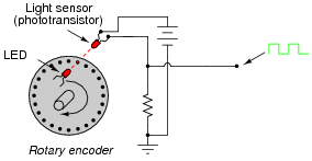
Rotary encoders are electromechanical devices used to convert an angular position (shaft rotation) into a digital signal. The simplest form of rotary encoder uses a slotted wheel with a single LED/photodetector pair to generate pulses as the wheel turns:
Some rotary encoder designs have multiple-bit outputs, with each LED/photodetector pair reading a different “track” of slots in the disk:

In the illustration shown above, identify which LED/photodetector pairs represent the MSB (Most Significant Bit) and LSB (Least Significant Bit) of the binary output. Also, identify which direction the wheel must turn in order to produce an increasing count.
Note: assume that the darkest areas on the illustration represent slots cut through the disk, while the grey areas represent parts of the disk that are opaque.
Reveal answerI’ll let you figure out the MSB, LSB, and up-count direction on your own! It isn’t difficult to do if you have mastered counting in binary.
Notes:Ask your students to brainstorm possible applications for rotary encoders. Where might we use such a device? Also, ask them to contrast the two encoder types (1 bit versus 3-bit) shown in the question. What applications might demand the 3-bit, versus only require a 1-bit encoder?
-
Question 3 of 12
Absolute rotary encoders often use a code known as Gray code rather than binary, to represent angular position. This code was patented by Frank Gray of Bell Labs in 1953, as a means of reducing errors in rotary encoder output. Examine each of these encoder disks, and determine which one is binary and which one is Gray code:
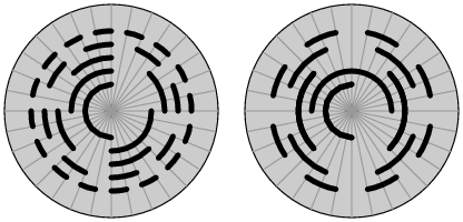
Assuming that the darkest areas on the illustration represent slots cut through the disk, and the grey areas represent parts of the disk that are opaque, mark the “zero,” “one,” and “two” sectors on each disk.
Reveal answer
I won’t directly tell you which disk is which, but I will provide a comparison of 5-bit binary versus Gray code, to help you in your analysis:
Binary Gray 00000 00000 00001 00001 00010 00011 00011 00010 00100 00110 00101 00111 00110 00101 00111 00100 01000 01100 01001 01101 01010 01111 01011 01110 01100 01010 01101 01011 01110 01001 01111 01000 10000 11000 10001 11001 10010 11011 10011 11010 10100 11110 10101 11111 10110 11101 10111 11100 11000 10100 11001 10101 11010 10111 11011 10110 11100 10010 11101 10011 11110 10001 11111 10000 Notes:Ask your students what patterns they notice in the Gray code sequence, as compared to the binary count. What difference do they see between binary and Gray code, analyzing the bit transitions from one number to the next?