Facebook
 Google
 GitHub
 Linkedin
DC Electric Circuits
Inductance
20 questions By Tony R. Kuphaldt
-
Question 1 of 20
∫f(x) dx Calculus alert!
One of the fundamental principles of calculus is a process called integration. This principle is important to understand because it is manifested in the behavior of inductance. Thankfully, there are more familiar physical systems which also manifest the process of integration, making it easier to comprehend.If we introduce a constant flow of water into a cylindrical tank with water, the water level inside that tank will rise at a constant rate over time:
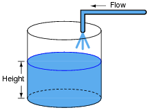
In calculus terms, we would say that the tank integrates water flow into water height. That is, one quantity (flow) dictates the rate-of-change over time of another quantity (height).
Like the water tank, electrical inductance also exhibits the phenomenon of integration with respect to time. Which electrical quantity (voltage or current) dictates the rate-of-change over time of which other quantity (voltage or current) in an inductance? Or, to re-phrase the question, which quantity (voltage or current), when maintained at a constant value, results in which other quantity (current or voltage) steadily ramping either up or down over time?
Reveal answerIn an inductance, current is the time-integral of voltage. That is, the applied voltage across the inductor dictates the rate-of-change of current through the inductor over time.
Challenge question: can you think of a way we could exploit the similarity of inductive voltage/current integration to simulate the behavior of a water tank’s filling, or any other physical process described by the same mathematical relationship?
Notes:The concept of integration doesn’t have to be overwhelmingly complex. Electrical phenomena such as capacitance and inductance may serve as excellent contexts in which students may explore and comprehend the abstract principles of calculus. The amount of time you choose to devote to a discussion of this question will depend on how mathematically adept your students are.
-
Question 2 of 20
Suppose a mass is connected to a winch by means of a cable, and a person turns the winch drum to raise the mass off the ground:
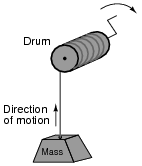
A physicist would likely look at this scenario as an example of energy exchange: the person turning the drum is expending energy, which in turn is being stored in the mass in potential form.
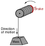
Suppose now that the person stops turning the drum and instead engages a brake mechanism on the drum so that it reverses rotation and slowly allows the mass to return to ground level. Once again, a physicist would view this scenario as an exchange of energy: the mass is now releasing energy, while the brake mechanism is converting that released energy into heat:
In each of the above scenarios, draw arrows depicting directions of two forces: the force that the mass exerts on the drum, and the force that the drum exerts on the mass. Compare these force directions with the direction of motion in each scenario, and explain how these directions relate to the mass and drum alternately acting as energy source and energy load.
Reveal answer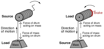
Follow-up question: although it may not be obvious, this question closely relates to the exchange of energy between components in electrical circuits! Explain this analogy.
Notes:Students typically find the concept of energy flow confusing with regard to electrical components. I try to make this concept clearer by using mechanical analogies, in which force and motion act as analog quantities to voltage and current (or visa-versa).
-
Question 3 of 20
Draw the direction of current in this circuit, and also identify the polarity of the voltage across the battery and across the resistor. Then, compare the battery’s polarity with the direction of current through it, and the resistor’s polarity with the direction of current through it.

What do you notice about the relationship between voltage polarity and current direction for these two different types of components? Identify the fundamental distinction between these two components that causes them to behave differently.
Reveal answerHere I show the answer in two different forms: current shown as electron flow (left) and current shown as conventional flow (right).
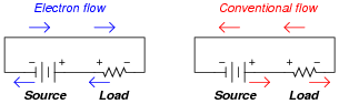
Whichever notation you choose to follow in your analysis of circuits, the understanding should be the same: the reason voltage polarities across the resistor and battery differ despite the same direction of current through both is the flow of power. The battery acts as a source, while the resistor acts as a load.
Notes:This type of distinction is very important in the study of physics as well, where one must determine whether a mechanical system is doing work or whether work is being done on it. A clear understanding of the relationship between voltage polarity and current direction for sources and loads is very important for students to have before they study reactive devices such as inductors and capacitors!