Facebook
 Google
 GitHub
 Linkedin
Network Analysis Techniques
Millman’s Theorem
9 questions By Tony R. Kuphaldt
-
Question 4 of 9
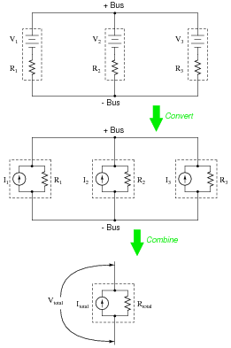
Write an algebraic equation that solves for the voltage between the two bus conductors, based on the problem-solving method of Thévenin-to-Norton conversion, combining Norton sources into one, and combining resistors into one:
Reveal answer
$$V_{total} = \frac{\frac{V_1}{R_1}+\frac{V_2}{R_2}+\frac{V_3}{R_3}}{\frac{1}{R_1}+\frac{1}{R_2}+\frac{1}{R_3}}$$
Notes:At first it may seem a bit overwhelming to derive an equation from these steps, but it is actually easier than it looks. A hint on how to do it: begin with the last step of the circuit simplification process, and work backwards as you elaborate your equation.
-
Question 5 of 9
Calculate the voltage indicated by the voltmeter in this circuit for the following voltage inputs:
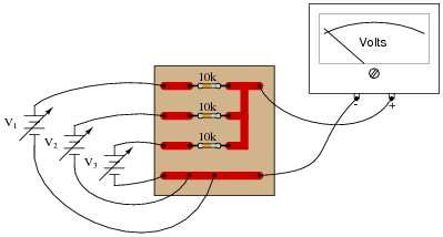
- V1 = 4.0 volts
- V2 = 5.0 volts
- V3 = 12.0 volts
What do you notice about the output voltage of this circuit? What mathematical function does this circuit perform?
Reveal answerVout = 7.0 volts
This circuit is a very simple form of analog computer, because it has the ability to perform a mathematical operation, with voltages representing numerical quantities!
Notes:Not only does this simple circuit provide an excellent opportunity to practice using Millman’s theorem, but it also illustrates the important principle of using resistor networks to perform mathematical functions. In essence, this circuit is a form of computer (an analog computer), capable of “calculating” at a rate of speed unmatched by any digital computer.
Ask your students to think of the advantages an analog computer such as this would have over a digital computer, and visa-versa. How come analog computers are seldom used, and digital technology is so prevalent? Does this mean analog computer technology has no place in modern electronics?
-
Question 6 of 9
Suppose this circuit was found to output a voltage of 11.0 volts, given the input voltages shown:
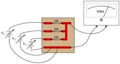
- V1 = 8.5 volts
- V2 = 10.0 volts
- V3 = 12.0 volts
What do suspect is wrong with this circuit? How would you verify the cause of the incorrect output voltage?
Reveal answerThe upper resistor is failed open.
Notes:Note how even with a failed resistor, the circuit still performs the proper mathematical function (albeit, only regarding two of the input “channels” rather than three). Ask your students how they determined the source of the problem, and how they would verify that as being the fault, with just a single meter measurement.