Facebook
 Google
 GitHub
 Linkedin
Digital Circuits
Multiplexers and Demultiplexers
15 questions By Tony R. Kuphaldt
-
Question 4 of 15
A variety of practical electronic applications require multiplexing, where several input signals are individually selected, one at a time but very rapidly, to be communicated through a single channel. Telephony systems use this technique to “concentrate” multiple voice conversations over a single wire pair, and most analog dual-trace oscilloscopes use this technique to allow a single-gun CRT to display more than one signal trace on the screen at a time.
In order to rapidly select (or switch) analog signals in these multiplexing applications, we need some form of semiconductor on/off switch capable of fast switching time, low pass-through (“on” state) impedance, and high blocking (“off” state) impedance. Thankfully, there is such a device commonly and inexpensively produced, called a CMOS bilateral switch:

This hybrid analog/digital device uses digital logic signals (high/low) to activate the gates of CMOS transistor assemblies to switch analog signals on and off. It is like having four low-current solid-state relays in a single integrated circuit. When the control line is made “high” (standard CMOS logic level), the respective switch goes into its conductive (“on”) state. When the control line is made “low,” the switch turns off. Because it is MOSFETs we are turning on and off, the control lines draw negligible current (just like CMOS logic gate inputs).
If we are to use such bilateral switches to multiplex analog signals along a common signal line, though, we must add some accessory components to control which switch (out of the four) is active at any given time. Take for instance this circuit where we use four bilateral switches to multiplex the voltage signals from four accelerometers (measuring acceleration on a vibration-testing jig):

Identify the necessary “mystery device” shown in the schematic, which allows a binary input (S0 and S1 with four combinations of high/low states: 00, 01, 10, and 11) to activate just one bilateral switch at a time.
Reveal answerThis “mystery device” is a 2-line to 4-line binary decoder.
Notes:This question serves a few purposes: to introduce students to the 4066 quad bilateral switch, to showcase a practical application for analog multiplexing, and to review a previous subject (decoders).
-
Question 5 of 15
Multiplexers and demultiplexers are often confused with one another by students first learning about them. Although they appear similar, they certainly perform different functions. Shown here is a multiplexer and a demultiplexer, each using a multiple-position switch symbol to indicate the selection functions inside the respective circuits:
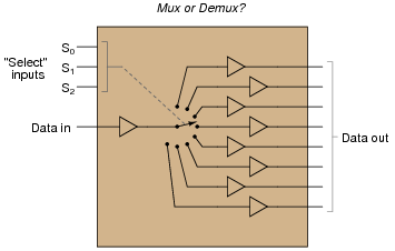
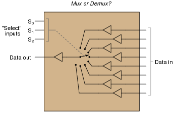
After identifying which is which, provide definitions for “multiplexer” and “demultiplexer” in your own words.
Reveal answerI’ll let you research the answer to this question on your own!
Notes:This question forces students to directly face a point of confusion I have noticed over several years of teaching. Ask them where they were able to find definitions for each term.
-
Question 6 of 15
The 74HC150 is a high-speed CMOS (TTL-compatible) integrated circuit multiplexer, also known as a data selector. It is commonly available as a 24 pin DIP “chip.” Identify the terminals of a 74HC150, and label them here:

In particular, note the locations of the four “select” terminals, as well as the single output terminal.
What types of electrical “data” may be “selected” by this particular integrated circuit? For example, can it select an analog waveform, such as human speech from a microphone? Is it limited to discrete TTL signals (low and high, 0 volts and 5 volts DC)? How can you tell?
Reveal answerDid you really think I would just show you the pinout here, instead of having you consult a datasheet? This is a discrete-signal device, only. It cannot “select” analog signals such as those involved in telephony.
Challenge question: how could you build an analog signal multiplexer, using components you are familiar with? I recommend you start with something simple, such as a four-channel multiplexer, before attempting something with as many channels as the digital device shown here (74HC150).
Notes:Datasheets not only provide basic pinout information, but they also reveal important operational characteristics of integrated circuits. In many cases they also show typical applications, which have great educational value. Stress the importance of datasheets to your students with “look-up” exercises such as this, build their ability to interpret the information contained.
In regard to the challenge question, it is a common mistake for students to think they can build an analog signal multiplexer around a digital signal multiplexer. In actuality, they would need a completely different type of device!