Facebook
 Google
 GitHub
 Linkedin
Digital Circuits
Multiplexers and Demultiplexers
15 questions By Tony R. Kuphaldt
-
Question 13 of 15
Predict how the operation of this “concentrator” circuit (which takes eight digital inputs and “concentrates” them into a single, multiplexed, communication line to be expanded into eight outputs at the receiving end) will be affected as a result of the following faults. Consider each fault independently (i.e. one at a time, no multiple faults):
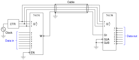
- Clock pulse generator stops pulsing:
- Pin breaks on the W output of 74151 chip, leaving that wire floating:
- Pin breaks on G2A input of 74138 chip, leaving it floating:
- Enable pin breaks on 74151 chip, leaving it floating:
For each of these conditions, explain why the resulting effects will occur.
Reveal answer- Clock pulse generator stops pulsing: Only one channel out of the eight will work, and it works all the time without interruption. Data cannot get through any of the other seven channels.
- Pin breaks on the W output of 74151 chip, leaving that wire floating: All selected outputs on the 74138 chip go low, instead of repeating the respective logic states input at the 74151 chip.
- Pin breaks on G2A input of 74138 chip, leaving it floating: All outputs on the 74138 chip go high, all the time.
- Enable pin breaks on 74151 chip, leaving it floating: All selected outputs on the 74138 chip go low, instead of repeating the respective logic states input at the 74151 chip.
Notes:The purpose of this question is to approach the domain of circuit troubleshooting from a perspective of knowing what the fault is, rather than only knowing what the symptoms are. Although this is not necessarily a realistic perspective, it helps students build the foundational knowledge necessary to diagnose a faulted circuit from empirical data. Questions such as this should be followed (eventually) by other questions asking students to identify likely faults based on measurements.
-
Question 14 of 15
Multiplexers, or data selectors, may be used to generate arbitrary truth table functions. Take for example this truth table, shown beside a symbol for a 16-channel multiplexer:

Show the wire connections necessary to make the multiplexer output the specified logic states in response to the data select (A, B, C, and D) inputs.
Reveal answer
Follow-up question: what if this multiplexer had an active-low output, like the 74150? How would this change your design for implementing the truth table?
Notes:Discuss with your students the significance of using a multiplexer in this fashion: to implement arbitrary logic functions. For those students who may not be familiar with the term, be sure to define the word “arbitrary.” It may seem silly, but students often fail to ask for the definitions of words that are new to them, for fear of sounding dumb in front of their peers and in front of you. One more reason to model respect in your classroom, and also to create an atmosphere where students feel comfortable asking any question.
-
Question 15 of 15
The following schematic diagram is for a two-input selector circuit, which (as the name implies) selects one of two inputs to be sent to the output:

Determine what state the “select control” input line has to be in to select InputA to be sent to the output, and what state it has to be in to select InputB to go to the output.
Reveal answerA high signal on the “select control” line selects InputA, while a low signal on that same line selects InputB.
Notes:Selector circuits are widely used internally in counter and shift register circuits where digital signals must be selected from multiple sources to achieve certain functions. Be sure your students understand how it works, for they will surely see it later in some application!