
 Facebook
 Google
 GitHub
 Linkedin
Basic Electricity
Ohm’s Law Practice Worksheet With Answers
23 questions By Tony R. Kuphaldt
-
Question 19 of 23
In this circuit, three resistors receive the same amount of voltage (24 volts) from a single source. Calculate the amount of current “drawn” by each resistor, as well as the amount of power dissipated by each resistor:

Reveal answerI1 Ω = 24 amps
I2 Ω = 12 amps
I3 Ω = 8 amps
P1 Ω = 576 watts
P2 Ω = 288 watts
P3 Ω = 192 watts
Notes:The answers to this question may seem paradoxical to students: the lowest value of resistor dissipates the greatest power. Math does not lie, though.
Another purpose of this question is to instill in students’ minds the concept of components in a simple parallel circuit all sharing the same amount of voltage.
Challenge your students to recognize any mathematical patterns in the respective currents and power dissipations. What can be said, mathematically, about the current drawn by the 2 Ω resistor versus the 1 Ω resistor, for example?
You might want to mention that in electrical parlance, a “heavy” load is one that draws a large amount of current, and thus has a large resistance. This circuit, which shows how the lowest resistance in a parallel circuit consumes the most power, gives practical support to the term “heavy” used to describe loads.
-
Question 20 of 23
The brightness of a light bulb - or the power dissipated by any electrical load, for that matter - may be varied by inserting a variable resistance in the circuit, like this:

This method of electrical power control is not without its disadvantages, though. Consider an example where the circuit current is 5 amps, the variable resistance is 2 Ω, and the lamp drops 20 volts of voltage across its terminals. Calculate the power dissipated by the lamp, the power dissipated by the variable resistance, and the total power provided by the voltage source. Then, explain why this method of power control is not ideal.
Reveal answerPlamp = 100 watts
Presistance = 50 watts
Ptotal = 150 watts
Follow-up question: note how in the original question I offered a set of hypothetical values to use in figuring out why a series rheostat (variable resistance) is not an efficient means to control lamp power. Explain how the assumption of certain values is a useful problem-solving technique in cases where no values are given to you.
Notes:Discuss the concept of energy conservation: that energy can neither be created nor destroyed, but merely changed between different forms. Based on this principle, the sum of all power dissipations in a circuit must equal the total amount of power supplied by the energy source, regardless of how the components are connected together.
-
Question 21 of 23
A modern method of electrical power control involves inserting a fast-operating switch in-line with an electrical load, to switch power on and off to it very rapidly over time. Usually, a solid-state device such as a transistor is used:
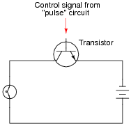
This circuit has been greatly simplified from that of a real, pulse-control power circuit. Just the transistor is shown (and not the “pulse” circuit which is needed to command it to turn on and off) for simplicity. All you need to be aware of is the fact that the transistor operates like a simple, single-pole single-throw (SPST) switch, except that it is controlled by an electrical current rather than by a mechanical force, and that it is able to switch on and off millions of times per second without wear or fatigue.
If the transistor is pulsed on and off fast enough, power to the light bulb may be varied as smoothly as if controlled by a variable resistor. However, there is very little energy wasted when using a fast-switching transistor to control electrical power, unlike when a variable resistance is used for the same task. This mode of electrical power control is commonly referred to as Pulse-Width Modulation, or PWM.
Explain why PWM power control is much more efficient than controlling load power by using a series resistance.
Reveal answerWhen the transistor is on, is acts like a closed switch: passing full load current, but dropping little voltage. Thus, its “ON” power \((P = I E)\) dissipation is minimal. Conversely, when the transistor is off, it acts like an open switch: passing no current at all. Thus, its “OFF” power dissipation \((P = I E)\) is zero. The power dissipated by the load (the light bulb) is the time-averaged power dissipated between “ON” and “OFF” transistor cycles. Thus, load power is controlled without “wasting” power across the control device.
Notes:Students may have a hard time grasping how a light bulb may be dimmed by turning it on and off really fast. The key to understanding this concept is to realize that the transistor’s switching time must be much faster than the time it takes for the light bulb’s filament to fully heat or fully cool. The situation is analogous to throttling the speed of an automobile by rapidly “pumping” the accelerator pedal. If done slowly, the result is a varying car speed. If done rapidly enough, though, the car’s mass averages the “ON”/“OFF” cycling of the pedal and results in a nearly steady speed.
This technique is very popular in industrial power control, and is gaining popularity as an audio amplification technique (known as Class D). The benefits of minimal wasted power by the control device are many.






The questions are very interesting.